
Lexus ES: Components
Lexus ES (XZ10) Service Manual / Vehicle Exterior / Lighting (ext) / Rear Light Assembly / Components
COMPONENTS
ILLUSTRATION
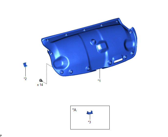
| *A | w/ Power Trunk Lid System | - | - |
| *1 | LUGGAGE COMPARTMENT DOOR COVER | *2 | LUGGAGE LOCK CONTROL CABLE PLATE |
| *3 | SWITCH BEZEL | - | - |
ILLUSTRATION
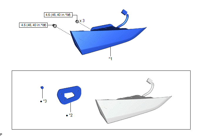
| *1 | REAR LIGHT ASSEMBLY | *2 | REAR LIGHT GASKET |
| *3 | REAR LIGHT PROTECTOR | - | - |
.png) | N*m (kgf*cm, ft.*lbf): Specified torque | ● | Non-reusable part |
READ NEXT:
 Removal
REMOVAL CAUTION / NOTICE / HINT HINT:
Use the same procedure for the RH side and LH side.
The following procedure is for the LH side.
PROCEDURE 1. REMOVE LUGGAGE LOCK CONTROL CABLE PLATE Click
Disassembly
DISASSEMBLY CAUTION / NOTICE / HINT HINT:
Use the same procedure for the RH side and LH side.
The following procedure is for the LH side.
PROCEDURE 1. REMOVE REAR LIGHT GASKET (a) Remove th
Inspection
INSPECTION PROCEDURE 1. INSPECT REAR LIGHT ASSEMBLY LH *a Component without harness connected (Rear Light Assembly LH) (a) Apply auxiliary battery voltage to the rear light assembly LH and ch
SEE MORE:
Front Camera Response Malfunction (C2A6D)
DESCRIPTION During self diagnosis of the parking assist ECU, the parking assist ECU sends display mode ID signals to the front television camera assembly. This DTC is stored when the output of the front television camera assembly does not match the expected output. DTC No. Detection Item DTC
Dcm Operation History
DCM OPERATION HISTORY DCM OPERATION HISTORY HINT:
This function shows the telematics network status when the DCM (telematics transceiver) was operated. Use this when no DTC is present but this telematics system was unable to connect to the call center. This symptom may occur if cell phone signal
© 2016-2026 Copyright www.lexguide.net
