Lexus ES: Removal
REMOVAL
PROCEDURE
1. CHANGE POWER TILT AND POWER TELESCOPIC STEERING COLUMN SYSTEM SETTINGS (for Power Tilt and Power Telescopic Steering Column)
Click here .gif)
2. REMOVE LOWER STEERING COLUMN COVER SUB-ASSEMBLY
Click here
3. REMOVE UPPER STEERING COLUMN COVER
Click here
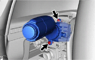
4. REMOVE TURN SIGNAL SWITCH
| (a) Remove the 2 screws. |
|
(b) Using a screwdriver with its tip wrapped with protective tape, disengage the claw and remove the turn signal switch as shown in the illustration.
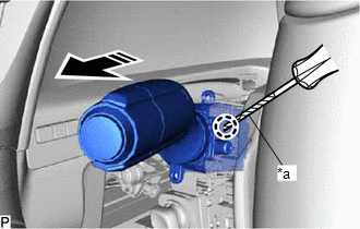
| *a | Protective Tape |
.png) | Remove in this Direction |
NOTICE:
If the claw is pulled with excessive force, it may break.
READ NEXT:
 Inspection
INSPECTION PROCEDURE 1. INSPECT TURN SIGNAL SWITCH (a) Measure the resistance according to the value(s) in the table below. Standard Resistance: Light Control Switch Tester Connection Conditi
Installation
INSTALLATION PROCEDURE 1. INSTALL TURN SIGNAL SWITCH (a) Engage the claw as shown in the illustration. Install in this Direction (b) Install the turn signal switch with the 2 screws. 2. INST
SEE MORE:
Active Noise Control ECU Communication Stop Mode
DESCRIPTION Detection Item Symptom Trouble Area Active Noise Control ECU Communication Stop Mode Any of the following conditions are met:
Communication stop for "Active Noise Control" is indicated on the "Communication Bus Check" screen of the Techstream.
Click here
Communicatio
Outside Air Temperature Sensor (C1652)
DESCRIPTION When a malfunction signal sent from the air conditioning system via CAN communication is detected by the clearance warning ECU assembly, DTC C1652 is stored. DTC No. Detection Item DTC Detection Condition Trouble Area C1652 Outside Air Temperature Sensor Ambient temperat
© 2016-2026 Copyright www.lexguide.net
