Lexus ES: Check Bus 2 Line for Short to GND
DESCRIPTION
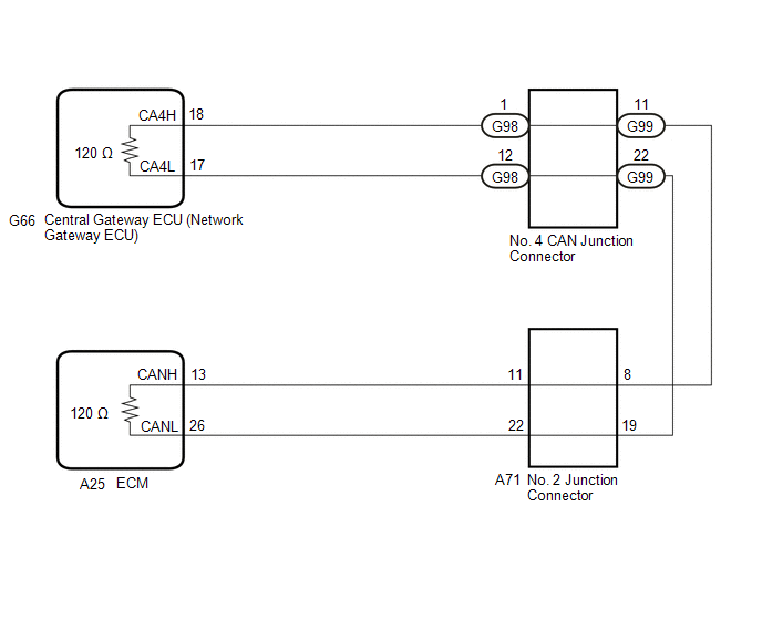
There may be a short circuit between one of the CAN bus lines and GND when there is no resistance between terminal 18 (CA4H) of the central gateway ECU (network gateway ECU) and terminal 4 (CG) of the DLC3, or terminal 17 (CA4L) of the central gateway ECU (network gateway ECU) and terminal 4 (CG) of the DLC3.
| Symptom | Trouble Area |
|---|---|
| There is no resistance between terminal 18 (CA4H) of the central gateway ECU (network gateway ECU) and terminal 4 (CG) of the DLC3, or terminal 17 (CA4L) of the central gateway ECU (network gateway ECU) and terminal 4 (CG) of the DLC3. |
|
WIRING DIAGRAM
CAUTION / NOTICE / HINT
CAUTION:
When performing the confirmation driving pattern, obey all speed limits and traffic laws.
NOTICE:
-
Because the order of diagnosis is important to allow correct diagnosis, make sure to begin troubleshooting using How to Proceed with Troubleshooting when CAN communication system related DTCs are output.
Click here
.gif)
- Before measuring the resistance of the CAN bus, turn the engine switch off and leave the vehicle for 1 minute or more without operating the key or any switches, or opening or closing the doors. After that, disconnect the cable from the negative (-) battery terminal and leave the vehicle for 1 minute or more before measuring the resistance.
-
After turning the engine switch off, waiting time may be required before disconnecting the cable from the negative (-) battery terminal. Therefore, make sure to read the disconnecting the cable from the negative (-) battery terminal notices before proceeding with work.
Click here
-
After performing repairs, perform the DTC check procedure and confirm that the DTCs are not output again.
DTC check procedure: Turn the engine switch on (IG) and wait for 1 minute or more. Then operate the suspected malfunctioning system and drive the vehicle at 60 km/h (37 mph) or more for 5 minutes or more.
-
After the repair, perform the CAN bus check and check that all the ECUs and sensors connected to the CAN communication system are displayed as normal.
Click here
HINT:
- Before disconnecting related connectors for inspection, push in on each connector body to check that the connector is not loose or disconnected.
- When a connector is disconnected, check that the terminals and connector body are not cracked, deformed or corroded.
PROCEDURE
| 1. | CHECK FOR SHORT TO GND IN CAN BUS LINE (NO. 2 JUNCTION CONNECTOR) |
(a) Disconnect the cable from the negative (-) battery terminal.
(b) Disconnect the A71 No. 2 junction connector.
(c) Measure the resistance according to the value(s) in the table below.
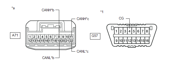
| *1 | DLC3 | - | - |
| *a | Front view of wire harness connector (to No. 2 Junction Connector) | *b | to No. 4 CAN Junction Connector |
| *c | to ECM | - | - |
Standard Resistance:
| Tester Connection | Condition | Specified Condition | Connected to |
|---|---|---|---|
| A71-8 (CANH) - G57-4 (CG) | Cable disconnected from negative (-) battery terminal | 200 Ω or higher | No. 4 CAN junction connector |
| A71-19 (CANL) - G57-4 (CG) | |||
| A71-11 (CANH) - G57-4 (CG) | Cable disconnected from negative (-) battery terminal | 200 Ω or higher | ECM |
| A71-22 (CANL) - G57-4 (CG) |
| Result | Proceed to |
|---|---|
| OK | A |
| NG (Line to ECM) | B |
| NG (Line to No. 4 CAN junction connector) | C |
| A | .gif) | REPLACE NO. 2 JUNCTION CONNECTOR |
| C | | GO TO STEP 3 |
|
.gif)
| 2. | CHECK FOR SHORT TO GND IN CAN BUS LINE (NO. 2 JUNCTION CONNECTOR - ECM) |
(a) Disconnect the A25 ECM connector.
(b) Measure the resistance according to the value(s) in the table below.
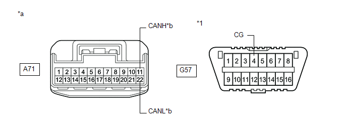
| *1 | DLC3 | - | - |
| *a | Front view of wire harness connector (to No. 2 Junction Connector) | *b | to ECM |
Standard Resistance:
| Tester Connection | Condition | Specified Condition |
|---|---|---|
| A71-11 (CANH) - G57-4 (CG) | Cable disconnected from negative (-) battery terminal | 200 Ω or higher |
| A71-22 (CANL) - G57-4 (CG) |
| OK | | REPLACE ECM |
| NG | | REPAIR OR REPLACE CAN MAIN BUS LINE OR CONNECTOR (NO. 2 JUNCTION CONNECTOR - ECM) |
| 3. | CHECK FOR SHORT TO GND IN CAN BUS LINE (NO. 4 CAN JUNCTION CONNECTOR - NO. 2 JUNCTION CONNECTOR) |
(a) Disconnect the G99 No. 4 CAN junction connector.
(b) Measure the resistance according to the value(s) in the table below.
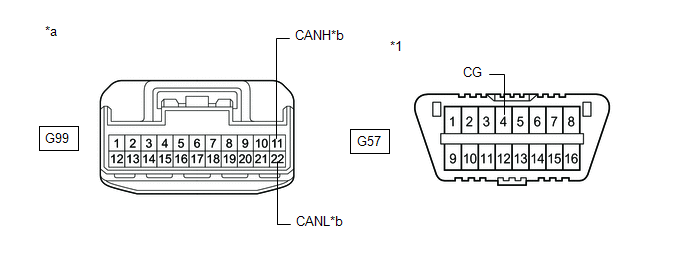
| *1 | DLC3 | - | - |
| *a | Front view of wire harness connector (to No. 4 CAN Junction Connector) | *b | to No. 2 Junction Connector |
Standard Resistance:
| Tester Connection | Condition | Specified Condition |
|---|---|---|
| G99-11 (CANH) - G57-4 (CG) | Cable disconnected from negative (-) battery terminal | 200 Ω or higher |
| G99-22 (CANL) - G57-4 (CG) |
| NG | | REPAIR OR REPLACE CAN MAIN BUS LINE OR CONNECTOR (NO. 4 CAN JUNCTION CONNECTOR - NO. 2 JUNCTION CONNECTOR) |
|
| 4. | CHECK FOR SHORT TO GND IN CAN BUS LINE (NO. 4 CAN JUNCTION CONNECTOR) |
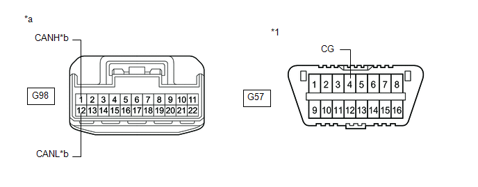
(a) Disconnect the G98 No. 4 CAN junction connector.
(b) Measure the resistance according to the value(s) in the table below.

| *1 | DLC3 | - | - |
| *a | Front view of wire harness connector (to No. 4 CAN Junction Connector) | *b | to Central Gateway ECU (Network Gateway ECU) |
Standard Resistance:
| Tester Connection | Condition | Specified Condition |
|---|---|---|
| G98-1 (CANH) - G57-4 (CG) | Cable disconnected from negative (-) battery terminal | 200 Ω or higher |
| G98-12 (CANL) - G57-4 (CG) |
| OK | | REPLACE NO. 4 CAN JUNCTION CONNECTOR |
|
| 5. | CHECK FOR SHORT TO GND IN CAN BUS LINE (NO. 4 CAN JUNCTION CONNECTOR - CENTRAL GATEWAY ECU (NETWORK GATEWAY ECU)) |
(a) Disconnect the G66 central gateway ECU (network gateway ECU) connector.
(b) Measure the resistance according to the value(s) in the table below.
| *1 | DLC3 | - | - |
| *a | Front view of wire harness connector (to No. 4 CAN Junction Connector) | *b | to Central Gateway ECU (Network Gateway ECU) |
Standard Resistance:
| Tester Connection | Condition | Specified Condition |
|---|---|---|
| G98-1 (CANH) - G57-4 (CG) | Cable disconnected from negative (-) battery terminal | 200 Ω or higher |
| G98-12 (CANL) - G57-4 (CG) |
| OK | | REPLACE CENTRAL GATEWAY ECU (NETWORK GATEWAY ECU) |
| NG | | REPAIR OR REPLACE CAN MAIN BUS LINE OR CONNECTOR (NO. 4 CAN JUNCTION CONNECTOR - CENTRAL GATEWAY ECU (NETWORK GATEWAY ECU)) |
READ NEXT:
 Check Bus 2 Line for Short to +B
DESCRIPTION There may be a short circuit between one of the CAN bus lines and +B when there is no resistance between terminal 18 (CA4H) of the central gateway ECU (network gateway ECU) and terminal 16
Check Bus 2 Lines for Short Circuit
DESCRIPTION There may be a short circuit between the CAN main bus lines and/or CAN branch lines when the resistance between terminals 18 (CA4H) and 17 (CA4L) of the central gateway ECU (network gatewa
Open in Bus 2 Main Bus Line
DESCRIPTION There may be an open circuit in one of the CAN main bus lines when the resistance between terminals 18 (CA4H) and 17 (CA4L) of the central gateway ECU (network gateway ECU) is 70 Ω or hig
SEE MORE:
Relay
On-vehicle InspectionON-VEHICLE INSPECTION PROCEDURE 1. INSPECT HORN RELAY *a Component without harness connected (HORN Relay) (a) Measure the resistance according to the value(s) in the table below. Standard Resistance: Tester Connection Condition Specified Condition 3 - 5 A
Components
COMPONENTS ILLUSTRATION *1 NO. 1 ENGINE UNDER COVER *2 FRONT LOWER BUMPER ABSORBER *3 FRONT FENDER APRON SEAL LH *4 FRONT FENDER APRON SEAL RH *5 FRONT WHEEL OPENING EXTENSION PAD LH *6 FRONT WHEEL OPENING EXTENSION PAD RH *7 NO. 2 ENGINE UNDER COVER ASSEMBLY -
