Lexus ES: Components
COMPONENTS
ILLUSTRATION
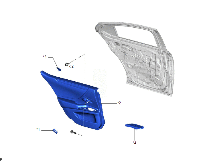
| *1 | COURTESY LIGHT ASSEMBLY | *2 | REAR DOOR TRIM BOARD SUB-ASSEMBLY |
| *3 | REAR DOOR UPPER TRIM PAD | *4 | REAR POWER WINDOW REGULATOR SWITCH ASSEMBLY WITH REAR DOOR UPPER ARMREST BASE PANEL |
ILLUSTRATION
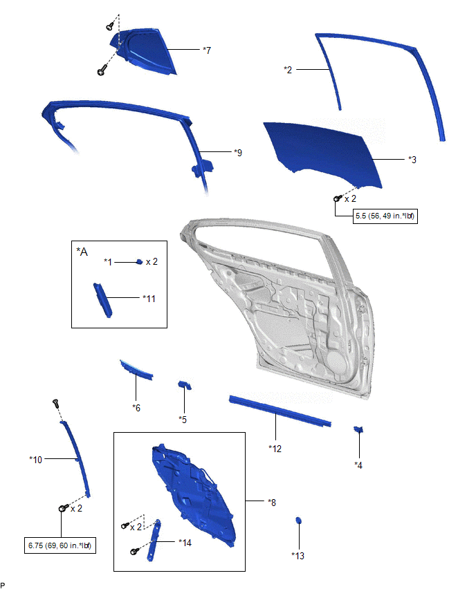
| *A | w/ Rear Door Sunshade | - | - |
| *1 | CURTAIN HOOK | *2 | REAR DOOR GLASS RUN |
| *3 | REAR DOOR GLASS SUB-ASSEMBLY | *4 | REAR DOOR NO. 2 SERVICE HOLE COVER |
| *5 | REAR DOOR NO. 2 VENT SEAL | *6 | REAR DOOR PANEL PROTECTOR |
| *7 | REAR DOOR QUARTER WINDOW GLASS SUB-ASSEMBLY | *8 | REAR DOOR SERVICE HOLE COVER |
| *9 | REAR DOOR WEATHERSTRIP | *10 | REAR DOOR WINDOW DIVISION BAR SUB-ASSEMBLY |
| *11 | REAR SIDE CURTAIN ASSEMBLY | *12 | REAR DOOR INNER GLASS WEATHERSTRIP |
| *13 | HOLE PLUG | *14 | BRACKET |
.png) | N*m (kgf*cm, ft.*lbf): Specified torque | - | - |
ILLUSTRATION
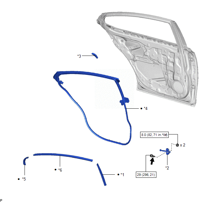
| *1 | FRONT INNER BLACK OUT TAPE | *2 | REAR DOOR CHECK ASSEMBLY |
| *3 | REAR DOOR FRAME GARNISH | *4 | REAR DOOR WEATHERSTRIP |
| *5 | REAR INNER BLACK OUT TAPE | *6 | UPPER INNER BLACK OUT TAPE |
| | N*m (kgf*cm, ft.*lbf): Specified torque | ● | Non-reusable part |
.png) | Toyota Genuine Adhesive 1324, Three Bond 1324 or equivalent | ★ | Precoated part |
READ NEXT:
 Removal
REMOVAL CAUTION / NOTICE / HINT The necessary procedures (adjustment, calibration, initialization, or registration) that must be performed after parts are removed and installed, or replaced during bla
Installation
INSTALLATION CAUTION / NOTICE / HINT HINT:
Use the same procedure for the RH side and LH side.
The following procedure is for the LH side.
PROCEDURE 1. PRECAUTION NOTICE: After turning the eng
SEE MORE:
Removal
REMOVAL CAUTION / NOTICE / HINT The necessary procedures (adjustment, calibration, initialization or registration) that must be performed after parts are removed and installed, or replaced during engine water pump assembly removal/installation are shown below. Necessary Procedure After Parts Removed
Components
COMPONENTS ILLUSTRATION *1 COOL AIR INTAKE DUCT SEAL *2 ENGINE COOLANT TEMPERATURE SENSOR *3 INLET AIR CLEANER ASSEMBLY *4 NO. 2 ENGINE COOLANT TEMPERATURE SENSOR N*m (kgf*cm, ft.*lbf): Specified torque ● Non-reusable part
