Lexus ES: Installation
INSTALLATION
CAUTION / NOTICE / HINT
HINT:
- Use the same procedure for the RH side and LH side.
- The following procedure is for the LH side.
PROCEDURE
1. PRECAUTION
NOTICE:
After turning the engine switch (for Gasoline Model) or power switch (for HV Model) off, waiting time may be required before disconnecting the cable from the negative (-) auxiliary battery terminal. Therefore, make sure to read the disconnecting the cable from the negative (-) auxiliary battery terminal notices before proceeding with work.
Click here .gif)
2. REPAIR INSTRUCTION
Click here
3. INSTALL REAR INNER BLACK OUT TAPE
(a) Refer to the illustration to position a new rear inner black out tape.
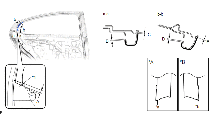
| *A | LH Side | *B | RH Side |
| *1 | Rear Door Weatherstrip | - | - |
| *a | Straight | *b | Triangle |
Standard Measurement:
| Area | Measurement | Area | Measurement |
|---|---|---|---|
| A | 5.0 mm (0.197 in.) | B | 0.6 mm (0.0236 in.) |
| C | 1.2 mm (0.0472 in.) | D | 1.0 mm (0.0394 in.) |
| E | 0 mm (0 in.) | - | - |
(b) Remove the release paper and install the rear inner black out tape.
4. INSTALL UPPER INNER BLACK OUT TAPE
(a) Refer to the illustration to position a new upper inner black out tape.
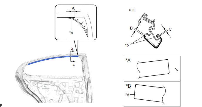
| *A | LH Side | *B | RH Side |
| *a | Rib of Rear Door Frame Garnish | *b | Edge of Curved Surface |
| *c | Straight | *d | Triangle |
Standard Measurement:
| Area | Measurement | Area | Measurement |
|---|---|---|---|
| A | 6.7 mm (0.264 in.) | B | 1.5 mm (0.0591 in.) |
| C | 1.0 mm (0.0394 in.) | - | - |
(b) Remove the release paper and install the upper inner black out tape.
5. INSTALL FRONT INNER BLACK OUT TAPE
(a) Refer to the illustration to position a new front inner black out tape.
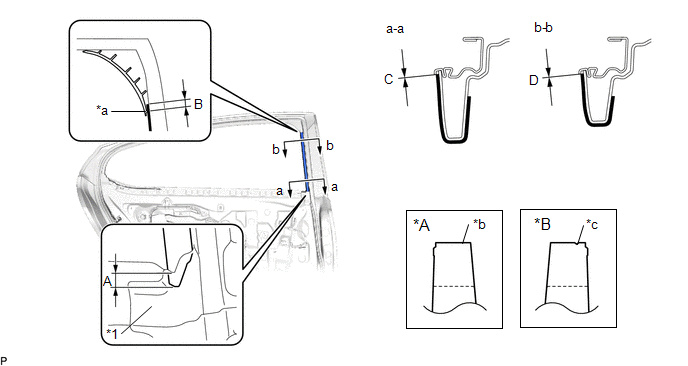
| *A | LH Side | *B | RH Side |
| *1 | Rear Door Weatherstrip | - | - |
| *a | Rib of Rear Door Frame Garnish | *b | Straight |
| *c | Triangle | - | - |
Standard Measurement:
| Area | Measurement | Area | Measurement |
|---|---|---|---|
| A | 8.0 mm (0.315 in.) | B | 6.7 mm (0.264 in.) |
| C | 0 mm (0 in.) | D | 0 mm (0 in.) |
(b) Remove the release paper and install the front inner black out tape.
6. INSTALL REAR DOOR WEATHERSTRIP
Click here
7. INSTALL REAR DOOR CHECK ASSEMBLY
Click here
8. INSTALL REAR DOOR FRAME GARNISH
Click here
9. INSTALL REAR DOOR GLASS SUB-ASSEMBLY
Click here
10. INSTALL REAR DOOR QUARTER WINDOW GLASS SUB-ASSEMBLY
Click here
11. INSTALL REAR DOOR WINDOW DIVISION BAR SUB-ASSEMBLY
Click here
12. CONNECT REAR DOOR WEATHERSTRIP
Click here
13. INSTALL REAR DOOR GLASS RUN
Click here
14. INSTALL REAR DOOR PANEL PROTECTOR
Click here
15. INSTALL REAR DOOR NO. 2 VENT SEAL
Click here
16. INSTALL REAR DOOR NO. 2 SERVICE HOLE COVER
Click here
17. INSTALL REAR DOOR SERVICE HOLE COVER
Click here
18. INSTALL CURTAIN HOOK (w/ Rear Door Sunshade)
Click here
19. INSTALL REAR SIDE CURTAIN ASSEMBLY (w/ Rear Door Sunshade)
Click here
20. INSTALL REAR DOOR TRIM BOARD SUB-ASSEMBLY
Click here
21. INSTALL COURTESY LIGHT ASSEMBLY
Click here
22. INSTALL REAR DOOR TRIM UPPER PAD
Click here
23. INSTALL REAR POWER WINDOW REGULATOR SWITCH ASSEMBLY WITH REAR DOOR UPPER ARMREST BASE PANEL
Click here
24. CONNECT CABLE TO NEGATIVE AUXILIARY BATTERY TERMINAL
for 2GR-FKS:
Click here
for A25A-FXS:
Click here
for A25A-FKS:
Click here
25. INITIALIZE POWER WINDOW CONTROL SYSTEM
for HV Model:
Click here
for Gasoline Model:
Click here
26. INSPECT POWER WINDOW OPERATION
for HV Model:
Click here
for Gasoline Model:
Click here
READ NEXT:
 Components
COMPONENTS ILLUSTRATION *1 COOL AIR INTAKE DUCT SEAL *2 FRONT BUMPER ASSEMBLY *3 FRONT BUMPER SIDE MOUNTING BRACKET - - ILLUSTRATION *A for Bar Type Radiator Grille -
Removal
REMOVAL CAUTION / NOTICE / HINT The necessary procedures (adjustment, calibration, initialization, or registration) that must be performed after parts are removed and installed, or replaced during fro
SEE MORE:
Components
COMPONENTS ILLUSTRATION *1 COWL TOP PANEL INSULATOR *2 FRONT FENDER SPLASH SHIELD SUB-ASSEMBLY *3 HEADLIGHT ASSEMBLY - - N*m (kgf*cm, ft.*lbf): Specified torque - - ILLUSTRATION *A for TMC Made - - *1 FRONT SIDE MARKER LIGHT BULB *2 FRONT TURN SI
EPS Warning Light Circuit
CAUTION / NOTICE / HINT NOTICE:
Perform this troubleshooting procedure when no DTCs are output, including DTCs related to CAN communication system malfunctions.
If the customer reports that the steering feels heavy, refer to the "Heavy steering" item in the Problem Symptoms Table.
Click here
