Lexus ES: Components
COMPONENTS
ILLUSTRATION
.png)
| *1 | LUGGAGE COMPARTMENT FLOOR MAT | *2 | SPARE WHEEL COVER TRAY |
ILLUSTRATION
.png)
| *1 | REAR FLOOR FINISH PLATE | *2 | LUGGAGE HOLD BELT STRIKER ASSEMBLY |
ILLUSTRATION
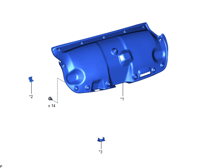
| *1 | LUGGAGE COMPARTMENT DOOR COVER | *2 | LUGGAGE LOCK CONTROL CABLE PLATE |
| *3 | SWITCH BEZEL | - | - |
ILLUSTRATION

| *A | for Type A | *B | for Type B |
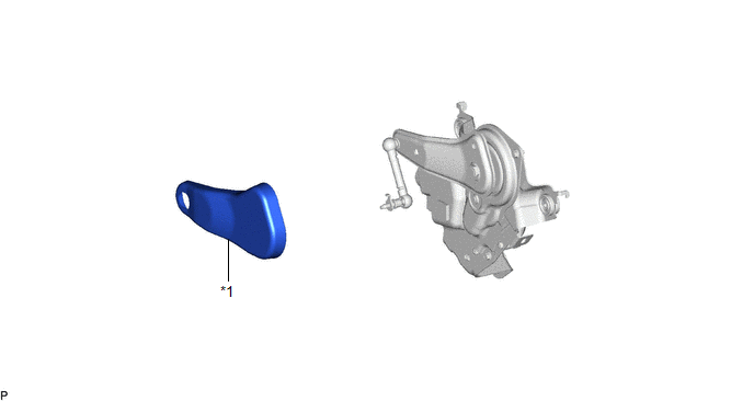
| *1 | LUGGAGE CLOSER MOTOR ASSEMBLY | *2 | LUGGAGE COMPARTMENT DOOR HINGE COVER RH |
| *3 | LUGGAGE COMPARTMENT TRIM COVER RH | *4 | LUGGAGE COMPARTMENT TRIM INNER COVER RH |
| *5 | ROPE HOOK | *6 | LUGGAGE HOLD BELT STRIKER ASSEMBLY |
.png) | N*m (kgf*cm, ft.*lbf): Specified torque | - | - |
ILLUSTRATION
| *1 | DECK SIDE TRIM COVER RH | - | - |
READ NEXT:
 Removal
REMOVAL CAUTION / NOTICE / HINT The necessary procedures (adjustment, calibration, initialization, or registration) that must be performed after parts are removed and installed, or replaced during lug
Installation
INSTALLATION PROCEDURE 1. INSTALL DECK SIDE TRIM COVER RH (a) Engage the clip to install the deck side trim cover RH. 2. INSTALL LUGGAGE CLOSER MOTOR ASSEMBLY (a) Connect the connector. (b) Engage the
SEE MORE:
Diagnosis System
DIAGNOSIS SYSTEM DESCRIPTION (a) Power window control system data and Diagnostic Trouble Codes (DTCs) can be read through the vehicle Data Link Connector 3 (DLC3). When the system seems to be malfunctioning, use the Techstream to check for malfunctions and perform repairs. CHECK DLC3 (a) Check the D
Inspection
INSPECTION PROCEDURE 1. INSPECT TILT AND TELESCOPIC SWITCH (a) Remove the tilt and telescopic switch. Click here (b) Measure the resistance according to the value(s) in the table below. Standard Resistance: Tester Connection Condition Specified Condition 1 (VC) - 3 (MSW) Tilt up
© 2016-2026 Copyright www.lexguide.net
