Lexus ES: Components
Lexus ES (XZ10) Service Manual / Audio & Visual & Telematics / Audio / Video / Radio Receiver / Components
COMPONENTS
ILLUSTRATION
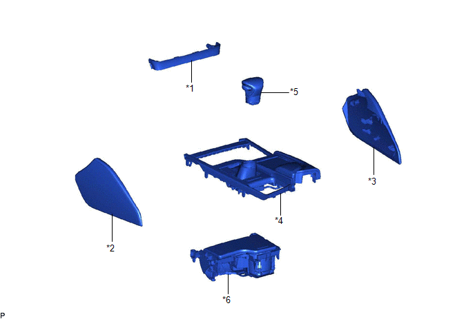
| *1 | CENTER INSTRUMENT CLUSTER FINISH PANEL SUB-ASSEMBLY | *2 | INSTRUMENT PANEL FINISH PANEL END LH |
| *3 | INSTRUMENT PANEL FINISH PANEL END RH | *4 | REAR UPPER CONSOLE PANEL SUB-ASSEMBLY |
| *5 | SHIFT LEVER KNOB SUB-ASSEMBLY | *6 | UPPER CONSOLE PANEL SUB-ASSEMBLY |
ILLUSTRATION
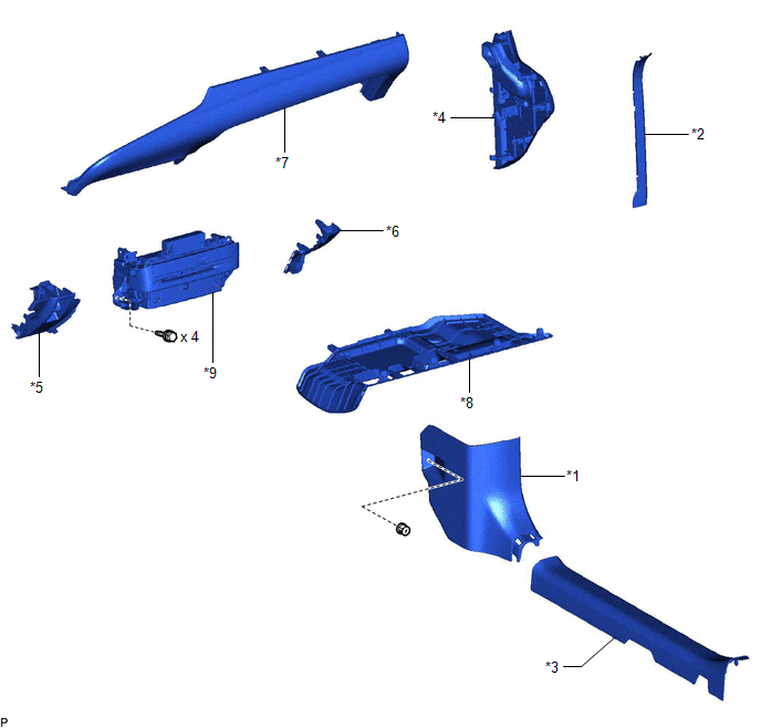
| *1 | COWL SIDE TRIM BOARD RH | *2 | FRONT DOOR OPENING TRIM COVER RH |
| *3 | FRONT DOOR SCUFF PLATE RH | *4 | INSTRUMENT SIDE PANEL RH |
| *5 | LOWER INSTRUMENT PANEL | *6 | LOWER INSTRUMENT PANEL LH |
| *7 | LOWER INSTRUMENT PANEL SUB-ASSEMBLY | *8 | NO. 2 INSTRUMENT PANEL UNDER COVER SUB-ASSEMBLY |
| *9 | RADIO RECEIVER ASSEMBLY WITH SWITCH | - | - |
ILLUSTRATION
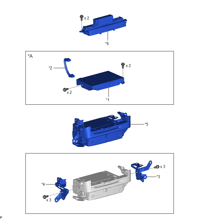
| *A | w/ Navigation System | - | - |
| *1 | NAVIGATION ECU WITH BRACKET | *2 | NO. 1 NAVIGATION WIRE |
| *3 | NO. 1 RADIO BRACKET | *4 | NO. 2 RADIO BRACKET |
| *5 | RADIO RECEIVER ASSEMBLY | *6 | REFRESHING SEAT SWITCH |
READ NEXT:
 Installation
INSTALLATION PROCEDURE 1. INSTALL NO. 2 RADIO BRACKET HINT: Perform this procedure only when replacement of the No. 2 radio bracket is necessary. (a) Install the No. 2 radio bracket with the 3 screws.
Installation
INSTALLATION PROCEDURE 1. INSTALL NO. 2 RADIO BRACKET HINT: Perform this procedure only when replacement of the No. 2 radio bracket is necessary. (a) Install the No. 2 radio bracket with the 3 screws.
Removal
REMOVAL PROCEDURE 1. PRECAUTION (for HV Model) (a) w/o Navigation System: NOTICE:
When replacing the radio receiver assembly, always replace it with a new one. If a radio receiver assembly which wa
SEE MORE:
Installation
INSTALLATION PROCEDURE 1. INSTALL PARKING ASSIST ECU (a) Turn back the front floor carpet assembly as shown in the illustration. (b) Engage the 2 guides to temporarily install the parking assist ECU as shown in the illustration. Install in this Direction (1) Install in t
How To Proceed With Troubleshooting
CAUTION / NOTICE / HINT HINT:
Use the following procedure to troubleshoot the audio and visual system.
*: Use the Techstream.
PROCEDURE 1. VEHICLE BROUGHT TO WORKSHOP
NEXT 2. CUSTOMER PROBLEM ANALYSIS
When troubleshooting, check that the problem symptoms
© 2016-2026 Copyright www.lexguide.net
