Lexus ES: Removal
REMOVAL
PROCEDURE
1. PRECAUTION (for HV Model)
(a) w/o Navigation System:
NOTICE:
-
When replacing the radio receiver assembly, always replace it with a new one. If a radio receiver assembly which was installed to another vehicle is used, the following may occur:
- A communication malfunction DTC may be stored.
- The radio receiver assembly may not operate normally.
NOTICE:
Click here .gif)
(b) w/ Navigation System:
NOTICE:
-
When replacing the radio receiver assembly or navigation ECU, always replace it with a new one. If a radio receiver assembly or navigation ECU which was installed to another vehicle is used, the following may occur:
- A communication malfunction DTC may be stored.
- The radio receiver assembly or navigation ECU may not operate normally.
- After replacing the radio receiver assembly, if the "New software is not compatible with the system. Contact your dealer." on-screen message is displayed on the multi-display assembly, update the software of the navigation ECU.
-
When performing the following work, the navigation system may restart when turning the power switch on (ACC) (due to radio receiver assembly and navigation ECU certification).
- Repair or replace the negative (-) auxiliary battery terminal due to it being disconnected or depleted.
- The radio receiver assembly or navigation ECU replacement or removal and installation.
NOTICE:
Click here
2. PRECAUTION (for Gasoline Model)
(a) w/o Navigation System:
NOTICE:
-
When replacing the radio receiver assembly, always replace it with a new one. If a radio receiver assembly which was installed to another vehicle is used, the following may occur:
- A communication malfunction DTC may be stored.
- The radio receiver assembly may not operate normally.
NOTICE:
Click here
(b) w/ Navigation System:
NOTICE:
-
When replacing the radio receiver assembly or navigation ECU, always replace it with a new one. If a radio receiver assembly or navigation ECU which was installed to another vehicle is used, the following may occur:
- A communication malfunction DTC may be stored.
- The radio receiver assembly or navigation ECU may not operate normally.
- After replacing the radio receiver assembly, if the "New software is not compatible with the system. Contact your dealer." on-screen message is displayed on the multi-display assembly, update the software of the navigation ECU.
-
When performing the following work, the navigation system may restart when turning the engine switch on (ACC) (due to radio receiver assembly and navigation ECU certification).
- Repair or replace the negative (-) battery terminal due to it being disconnected or depleted.
- The radio receiver assembly or navigation ECU replacement or removal and installation.
NOTICE:
Click here
3. REMOVE INSTRUMENT PANEL FINISH PANEL END LH
Click here
4. REMOVE INSTRUMENT PANEL FINISH PANEL END RH
Click here
5. REMOVE CENTER INSTRUMENT CLUSTER FINISH PANEL SUB-ASSEMBLY
Click here
6. REMOVE SHIFT LEVER KNOB SUB-ASSEMBLY
for UA80E: Click here
for P710: Click here
7. REMOVE REAR UPPER CONSOLE PANEL SUB-ASSEMBLY
Click here
8. REMOVE UPPER CONSOLE PANEL SUB-ASSEMBLY
Click here
9. REMOVE LOWER INSTRUMENT PANEL
Click here
10. REMOVE FRONT DOOR SCUFF PLATE RH
HINT:
Use the same procedure as for the LH side.
Click here
11. REMOVE COWL SIDE TRIM BOARD RH
HINT:
Use the same procedure as for the LH side.
Click here
12. REMOVE FRONT DOOR OPENING TRIM COVER RH
HINT:
Use the same procedure as for the LH side.
Click here
13. REMOVE INSTRUMENT SIDE PANEL RH
Click here
14. REMOVE NO. 2 INSTRUMENT PANEL UNDER COVER SUB-ASSEMBLY
Click here
15. REMOVE LOWER INSTRUMENT PANEL LH
Click here
16. REMOVE LOWER INSTRUMENT PANEL SUB-ASSEMBLY
Click here
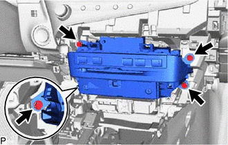
17. REMOVE RADIO RECEIVER ASSEMBLY WITH SWITCH
| (a) Remove the 4 bolts. |
|
(b) Pull the radio receiver assembly with switch to disengage the 4 claws.
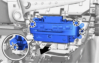
.png) | Remove in this Direction |
(c) Disconnect each connector and remove the radio receiver assembly with switch.
18. REMOVE REFRESHING SEAT SWITCH
Click here
19. REMOVE NO. 1 NAVIGATION WIRE (w/ Navigation System)
Click here
20. REMOVE NAVIGATION ECU WITH BRACKET (w/ Navigation System)
Click here
21. REMOVE RADIO RECEIVER ASSEMBLY
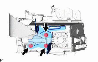
22. REMOVE NO. 1 RADIO BRACKET
HINT:
Perform this procedure only when replacement of the No. 1 radio bracket is necessary.
| (a) Remove the 3 screws and No. 1 radio bracket. |
|
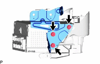
23. REMOVE NO. 2 RADIO BRACKET
HINT:
Perform this procedure only when replacement of the No. 2 radio bracket is necessary.
| (a) Remove the 3 screws and No. 2 radio bracket. |
|
READ NEXT:
 Removal
REMOVAL PROCEDURE 1. PRECAUTION (for HV Model) (a) w/o Navigation System: NOTICE:
When replacing the radio receiver assembly, always replace it with a new one. If a radio receiver assembly which wa
Components
COMPONENTS ILLUSTRATION *1 COURTESY LIGHT ASSEMBLY *2 REAR DOOR TRIM BOARD SUB-ASSEMBLY *3 REAR DOOR TRIM UPPER PAD *4 REAR POWER WINDOW REGULATOR SWITCH ASSEMBLY WITH REAR DOOR UP
SEE MORE:
Pressure Control Solenoid "B" Circuit Short to Battery (P077512)
DESCRIPTION Changing gears is performed by the ECM turning the solenoid (SL1, SL2, SL3, SL4, SL5 and SL6) valves on and off. If an open or short occurs in any of the solenoid valve circuits, the ECM controls the remaining normal solenoid valves to allow the vehicle to be driven. If all of the soleno
Front Radar Sensor Optical Axis Misalignment Malfunction (C1A1100)
DESCRIPTION The millimeter wave radar sensor assembly performs self-diagnosis to check for misalignment of its beam axis. If misalignment is detected, the millimeter wave radar sensor assembly stores DTC C1A1100. DTC No. Detection Item DTC Detection Condition Trouble Area C1A1100 Fron
