Lexus ES: Installation
INSTALLATION
PROCEDURE
1. INSTALL NO. 2 RADIO BRACKET
HINT:
Perform this procedure only when replacement of the No. 2 radio bracket is necessary.
(a) Install the No. 2 radio bracket with the 3 screws.
2. INSTALL NO. 1 RADIO BRACKET
HINT:
Perform this procedure only when replacement of the No. 1 radio bracket is necessary.
(a) Install the No. 1 radio bracket with the 3 screws.
3. INSTALL RADIO RECEIVER ASSEMBLY
4. INSTALL NAVIGATION ECU WITH BRACKET (w/ Navigation System)
Click here .gif)
5. INSTALL NO. 1 NAVIGATION WIRE (w/ Navigation System)
Click here
6. INSTALL REFRESHING SEAT SWITCH
Click here
7. INSTALL RADIO RECEIVER ASSEMBLY WITH SWITCH
(a) Connect each connector.
(b) Engage the 4 claws to temporarily install the radio receiver assembly with switch as shown in the illustration.
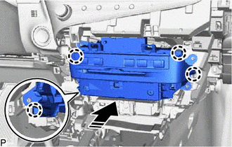
.png) | Install in this Direction |
(c) Install the radio receiver assembly with switch with the 4 bolts.
8. INSTALL LOWER INSTRUMENT PANEL SUB-ASSEMBLY
Click here
9. INSTALL LOWER INSTRUMENT PANEL LH
Click here
10. INSTALL NO. 2 INSTRUMENT PANEL UNDER COVER SUB-ASSEMBLY
Click here
11. INSTALL INSTRUMENT SIDE PANEL RH
Click here
12. INSTALL FRONT DOOR OPENING TRIM COVER RH
HINT:
Use the same procedure as for the LH side.
Click here
13. INSTALL COWL SIDE TRIM BOARD RH
HINT:
Use the same procedure as for the LH side.
Click here
14. INSTALL FRONT DOOR SCUFF PLATE RH
HINT:
Use the same procedure as for the LH side.
Click here
15. INSTALL LOWER INSTRUMENT PANEL
Click here
16. INSTALL UPPER CONSOLE PANEL SUB-ASSEMBLY
Click here
17. INSTALL REAR UPPER CONSOLE PANEL SUB-ASSEMBLY
Click here
18. INSTALL SHIFT LEVER KNOB SUB-ASSEMBLY
for UA80E: Click here
for P710: Click here
19. INSTALL CENTER INSTRUMENT CLUSTER FINISH PANEL SUB-ASSEMBLY
Click here
20. INSTALL INSTRUMENT PANEL FINISH PANEL END RH
Click here
21. INSTALL INSTRUMENT PANEL FINISH PANEL END LH
Click here
READ NEXT:
 Installation
INSTALLATION PROCEDURE 1. INSTALL NO. 2 RADIO BRACKET HINT: Perform this procedure only when replacement of the No. 2 radio bracket is necessary. (a) Install the No. 2 radio bracket with the 3 screws.
Removal
REMOVAL PROCEDURE 1. PRECAUTION (for HV Model) (a) w/o Navigation System: NOTICE:
When replacing the radio receiver assembly, always replace it with a new one. If a radio receiver assembly which wa
Removal
REMOVAL PROCEDURE 1. PRECAUTION (for HV Model) (a) w/o Navigation System: NOTICE:
When replacing the radio receiver assembly, always replace it with a new one. If a radio receiver assembly which wa
SEE MORE:
Inside rear view mirror
The rear view mirror's position can
be adjusted to enable sufficient
confirmation of the rear view.
Adjusting the height of rear view
mirror
The height of the rear view mirror can
be adjusted to suit your driving posture.
Adjust the height of the rear view mirror
by moving it up and down.
Installation
INSTALLATION CAUTION / NOTICE / HINT HINT: for Side:
Use the same procedure for the RH side and LH side.
The following procedure is for the LH side.
PROCEDURE 1. INSTALL FRONT NO. 3 SPEAKER ASSEMBLY (for Center) NOTICE: Do not touch the speaker cone. (a) Connect the connector. (b) Install
