Lexus ES: Components
COMPONENTS
ILLUSTRATION
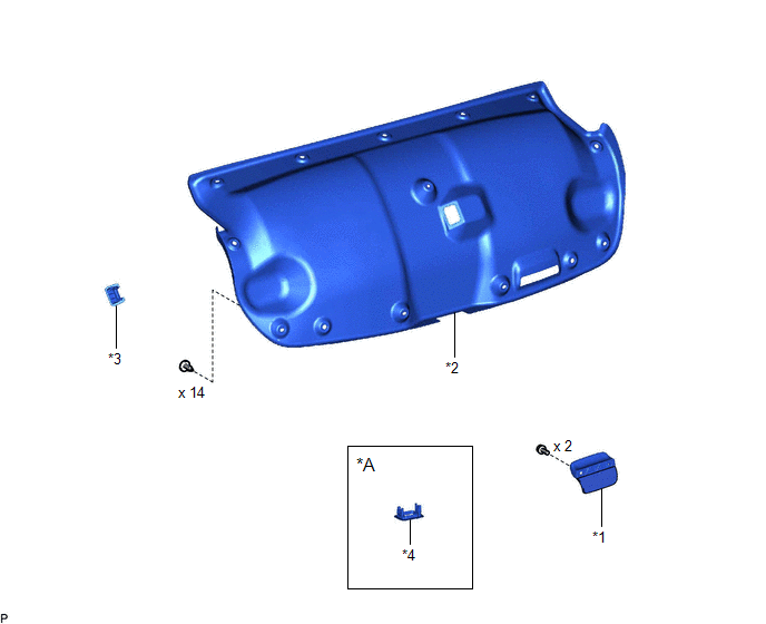
| *A | w/ Power Trunk Lid System | - | - |
| *1 | LUGGAGE COMPARTMENT DOOR ASSIST GRIP | *2 | LUGGAGE COMPARTMENT DOOR COVER |
| *3 | LUGGAGE LOCK CONTROL CABLE PLATE | *4 | SWITCH BEZEL |
ILLUSTRATION
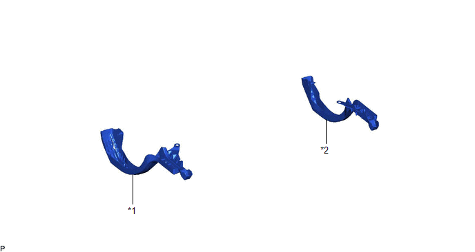
| *1 | LUGGAGE COMPARTMENT DOOR HINGE COVER LH | *2 | LUGGAGE COMPARTMENT DOOR HINGE COVER RH |
ILLUSTRATION
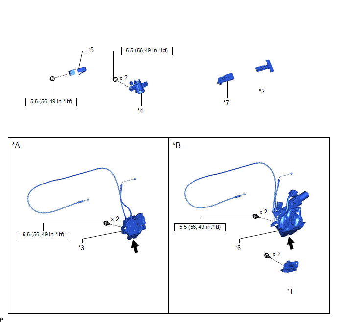
| *A | w/o Power Trunk Lid System | *B | w/ Power Trunk Lid System |
| *1 | DOOR CONTROL SWITCH | *2 | LUGGAGE COMPARTMENT DOOR INSIDE HANDLE |
| *3 | LUGGAGE COMPARTMENT DOOR LOCK ASSEMBLY | *4 | LUGGAGE COMPARTMENT DOOR LOCK CYLINDER ASSEMBLY |
| *5 | LUGGAGE COMPARTMENT KEY CYLINDER PROTECTOR | *6 | LUGGAGE DOOR CLOSER ASSEMBLY |
| *7 | LUGGAGE LOCK CONTROL CABLE CLAMP | - | - |
.png) | N*m (kgf*cm, ft.*lbf): Specified torque | .png) | MP grease |
ILLUSTRATION
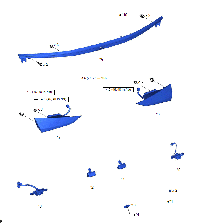
| *1 | HOLE PLUG | *2 | LICENSE PLATE LIGHT ASSEMBLY LH |
| *3 | LICENSE PLATE LIGHT ASSEMBLY RH | *4 | LUGGAGE COMPARTMENT DOOR CUSHION |
| *5 | LUGGAGE COMPARTMENT DOOR OUTSIDE GARNISH SUB-ASSEMBLY | *6 | LUGGAGE ELECTRICAL KEY SWITCH |
| *7 | REAR LIGHT ASSEMBLY LH | *8 | REAR LIGHT ASSEMBLY RH |
| *9 | TELEVISION CAMERA ASSEMBLY WITH WIRE | *10 | CLIP |
| | N*m (kgf*cm, ft.*lbf): Specified torque | ● | Non-reusable part |
ILLUSTRATION
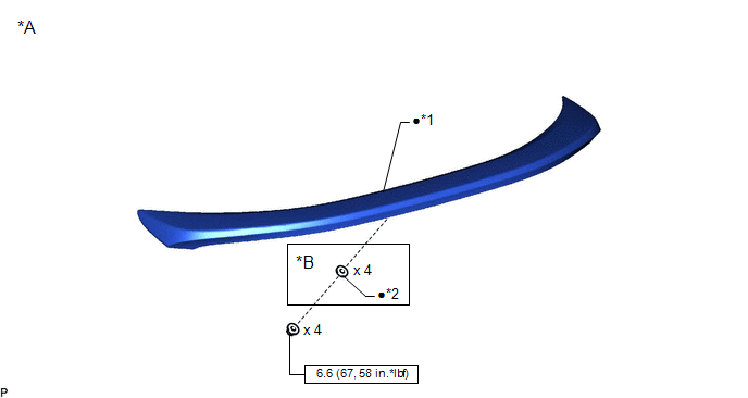
| *A | w/ Rear Spoiler | *B | for TMMK Made |
| *1 | REAR SPOILER SUB-ASSEMBLY | *2 | GASKET |
| | N*m (kgf*cm, ft.*lbf): Specified torque | ● | Non-reusable part |
READ NEXT:
 Disassembly
DISASSEMBLY CAUTION / NOTICE / HINT The necessary procedures (adjustment, calibration, initialization, or registration) that must be performed after parts are removed and installed, or replaced during
Adjustment
ADJUSTMENT CAUTION / NOTICE / HINT *a Centering Bolt *b Standard Bolt HINT:
Centering bolts are used to mount the door hinge to the door. The door cannot be adjusted with the centeri
Reassembly
REASSEMBLY PROCEDURE 1. INSTALL REAR SPOILER SUB-ASSEMBLY (w/ Rear Spoiler) Click here 2. INSTALL LICENSE PLATE LIGHT ASSEMBLY LH Click here 3. INSTALL LICENSE PLATE LIGHT ASSEMBLY RH HINT: Use th
SEE MORE:
Ignition Coil And Spark Plug
RemovalREMOVAL CAUTION / NOTICE / HINT The necessary procedures (adjustment, calibration, initialization or registration) that must be performed after parts are removed and installed, or replaced during ignition coil assembly or spark plug removal/installation are shown below. Necessary Procedures
Installation
INSTALLATION CAUTION / NOTICE / HINT NOTICE: This procedure includes the installation of small-head bolts. Refer to Small-Head Bolts of Basic Repair Hint to identify the small-head bolts. Click here PROCEDURE 1. INSTALL THROTTLE BODY GASKET (a) Install a new throttle body gasket to the intake m
