Lexus ES: System Diagram
Lexus ES (XZ10) Service Manual / Steering / Steering Column / Heated Steering Wheel System (for Hv Model) / System Diagram
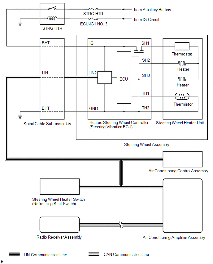
SYSTEM DIAGRAM
SYSTEM DIAGRAM
 Communication Table
 | Sender | Receiver | Signal | Line |
|---|---|---|---|
| Radio Receiver Assembly | Air Conditioning Amplifier Assembly |
| CAN |
READ NEXT:
 System Description
SYSTEM DESCRIPTION HEATED STEERING WHEEL SYSTEM (a) The heated steering wheel system heats the steering wheel assembly when the system is turned on using the steering wheel heater switch (refreshing s
How To Proceed With Troubleshooting
CAUTION / NOTICE / HINT HINT:
Use these procedures to troubleshoot the heated steering wheel system.
*: Use the Techstream.
PROCEDURE 1. VEHICLE BROUGHT TO WORKSHOP
NEXT
Customize Parameters
CUSTOMIZE PARAMETERS CUSTOMIZE HEATED STEERING WHEEL SYSTEM (a) Customizing with the Techstream. NOTICE:
When the customer requests a change in a function, first make sure that the function can be
SEE MORE:
Automatic High Beam Camera (B124C)
DESCRIPTION The main body ECU (multiplex network body ECU) detects a high beam headlight illumination request signal of the automatic high beam system from the forward recognition camera. DTC No. Detection Item DTC Detection Condition Trouble Area DTC Output from B124C Automatic Hig
Adjustment
ADJUSTMENT CAUTION / NOTICE / HINT *a Centering Bolt *b Standard Bolt HINT:
Centering bolts are used to install the hood hinges and hood lock. The hood and hood lock cannot be adjusted with the centering bolts installed. Substitute the centering bolts with standard bolts with washe
© 2016-2026 Copyright www.lexguide.net
