Lexus ES: Adjustment
ADJUSTMENT
CAUTION / NOTICE / HINT
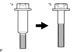
| *a | Centering Bolt |
| *b | Standard Bolt |
HINT:
- Centering bolts are used to mount the door hinge to the door. The door cannot be adjusted with the centering bolts installed. Substitute the centering bolts with standard bolts when making adjustments.
-
Specified torque for standard bolts is shown in the standard bolt chart.
Click here
.gif)
PROCEDURE
1. INSPECT LUGGAGE COMPARTMENT DOOR
(a) Check that the clearance measurements of areas a through e are within each standard range.
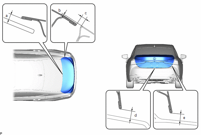 Standard Clearance
 | Area | Measurement | Area | Measurement |
|---|---|---|---|
| a | 5.05 mm (0.199 in.) | b | -0.8 to 2.2 mm (-0.0315 to 0.0866 in.) |
| c | 2.0 to 5.0 mm (0.0787 to 0.197 in.) | d | 3.2 to 5.9 mm (0.126 to 0.232 in.) |
| e | 3.2 to 5.9 mm (0.126 to 0.232 in.) | - | - |
2. REMOVE LUGGAGE COMPARTMENT FLOOR MAT
Click here
3. REMOVE SPARE WHEEL COVER TRAY
Click here
4. REMOVE REAR FLOOR FINISH PLATE
Click here
5. REMOVE LUGGAGE LOCK CONTROL CABLE PLATE
Click here
6. REMOVE SWITCH BEZEL (w/ Power Trunk Lid System)
Click here
7. REMOVE LUGGAGE COMPARTMENT DOOR COVER
Click here
8. REMOVE LUGGAGE COMPARTMENT DOOR HINGE COVER LH
Click here
9. REMOVE LUGGAGE COMPARTMENT DOOR HINGE COVER RH
HINT:
Use the same procedure as for the LH side.
10. ADJUST LUGGAGE COMPARTMENT DOOR
| (a) Loosen the 4 door side hinge bolts to adjust the door horizontally and vertically. |
|
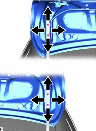
(b) Tighten the 4 bolts after adjustment.
Torque:
7.0 N·m {71 kgf·cm, 62 in·lbf}
| (c) Using a T40 "TORX" socket wrench, slightly loosen the 2 striker mounting screws. |
|
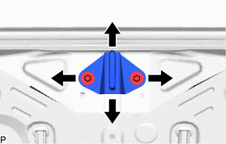
(d) Using a brass bar and a hammer, hit the striker to adjust its position.
(e) Using a T40 "TORX" socket wrench, tighten the 2 striker mounting screws after adjustment.
Torque:
23 N·m {235 kgf·cm, 17 ft·lbf}
11. INSTALL LUGGAGE COMPARTMENT DOOR HINGE COVER LH
Click here
12. INSTALL LUGGAGE COMPARTMENT DOOR HINGE COVER RH
HINT:
Use the same procedure as for the LH side.
13. INSTALL LUGGAGE COMPARTMENT DOOR COVER
Click here
14. INSTALL SWITCH BEZEL (w/ Power Trunk Lid System)
Click here
15. INSTALL LUGGAGE LOCK CONTROL CABLE PLATE
Click here
16. INSTALL REAR FLOOR FINISH PLATE
Click here
17. INSTALL SPARE WHEEL COVER TRAY
Click here
18. INSTALL LUGGAGE COMPARTMENT FLOOR MAT
Click here
READ NEXT:
 Reassembly
REASSEMBLY PROCEDURE 1. INSTALL REAR SPOILER SUB-ASSEMBLY (w/ Rear Spoiler) Click here 2. INSTALL LICENSE PLATE LIGHT ASSEMBLY LH Click here 3. INSTALL LICENSE PLATE LIGHT ASSEMBLY RH HINT: Use th
Luggage Compartment Door Closer Switch
ComponentsCOMPONENTS ILLUSTRATION *1 DOOR CONTROL SWITCH *2 LUGGAGE COMPARTMENT DOOR COVER *3 LUGGAGE LOCK CONTROL CABLE PLATE *4 SWITCH BEZEL RemovalREMOVAL PROCEDURE 1. REMO
SEE MORE:
Left Rear Wheel Speed Sensor Circuit Intermittent (C050C1F)
DESCRIPTION Refer to DTC C050C12 Click here DTC No. Detection Item DTC Detection Condition Trouble Area C050C1F Left Rear Wheel Speed Sensor Circuit Intermittent
The speed sensor signal is excessively noisy.
The calculated change in wheel speed is more than 980 m/s2 for 5*1 o
GPS Antenna Connection Malfunction(short) (B15C0,B15C1)
DESCRIPTION These DTCs are stored when a malfunction occurs in the navigation antenna assembly. DTC No. Detection Item DTC Detection Condition Trouble Area B15C0 GPS Antenna Connection Malfunction(short) GPS Antenna Connection Malfunction (short)
Navigation antenna assembly
A
