Lexus ES: Components
Lexus ES (XZ10) Service Manual / Suspension / Suspension Control / Front Acceleration Sensor / Components
COMPONENTS
ILLUSTRATION

| *A | for LH Side | - | - |
| *1 | COWL SIDE TRIM BOARD LH | *2 | FRONT DOOR OPENING TRIM COVER LH |
| *3 | FRONT DOOR SCUFF PLATE LH | *4 | INSTRUMENT SIDE PANEL LH |
| *5 | LOWER INSTRUMENT PANEL FINISH PANEL SUB-ASSEMBLY | *6 | NO. 1 INSTRUMENT PANEL UNDER COVER SUB-ASSEMBLY |
ILLUSTRATION

| *A | for RH Side | - | - |
| *1 | COWL SIDE TRIM BOARD RH | *2 | FRONT DOOR OPENING TRIM COVER RH |
| *3 | FRONT DOOR SCUFF PLATE RH | *4 | INSTRUMENT SIDE PANEL RH |
| *5 | LOWER INSTRUMENT FINISH SUB PANEL | - | - |
ILLUSTRATION
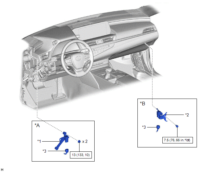
| *A | for LH Side | *B | for RH Side |
| *1 | ACCELERATION SENSOR ASSEMBLY LH | *2 | ACCELERATION SENSOR ASSEMBLY RH |
| *3 | CONNECTOR | - | - |
.png) | N*m (kgf*cm, ft.*lbf): Specified torque | - | - |
READ NEXT:
 Removal
REMOVAL PROCEDURE 1. REMOVE FRONT DOOR SCUFF PLATE LH (for LH Side) Click here 2. REMOVE COWL SIDE TRIM BOARD LH (for LH Side) Click here 3. REMOVE NO. 1 INSTRUMENT PANEL UNDER COVER SUB-ASSEMBL
Inspection
INSPECTION PROCEDURE 1. INSPECT ACCELERATION SENSOR ASSEMBLY (a) Connect 3 1.5 V dry cell batteries in series. (b) Connect a positive (+) lead from the batteries to terminal 3 and a negative (-) lead
Installation
INSTALLATION PROCEDURE 1. INSTALL ACCELERATION SENSOR ASSEMBLY LH (for LH Side) (a) Install the acceleration sensor assembly LH with the 2 nuts. Torque: 13 N·m {133 kgf·cm, 10 ft·lbf} NOTICE:
SEE MORE:
Removal
REMOVAL CAUTION / NOTICE / HINT The necessary procedures (adjustment, calibration, initialization, or registration) that must be performed after parts are removed and installed, or replaced during outer rear view mirror assembly with cover removal/installation are shown below. Necessary Procedure Af
Components
COMPONENTS ILLUSTRATION *A w/o AVS - - *1 FRONT AXLE ASSEMBLY *2 FRONT AXLE SHAFT NUT *3 FRONT DISC *4 FRONT DISC BRAKE CALIPER ASSEMBLY *5 FRONT DRIVE SHAFT ASSEMBLY *6 FRONT LOWER NO. 1 SUSPENSION ARM SUB-ASSEMBLY *7 FRONT SPEED SENSOR *8 TIE ROD A
© 2016-2026 Copyright www.lexguide.net
