Lexus ES: MIL Circuit
DESCRIPTION
The Malfunction Indicator Lamp (MIL) is used to indicate vehicle malfunctions detected by the ECM.
The MIL operation can be checked visually. When the power switch is first turned to on (IG), the MIL should be illuminated and should then turn off after the engine is started. If the MIL remains illuminated or is not illuminated, conduct the following troubleshooting procedure using the Techstream.
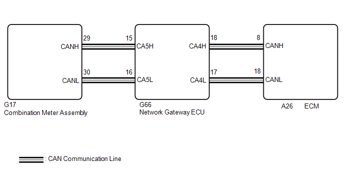
WIRING DIAGRAM
PROCEDURE
| 1. | CHECK THAT MIL IS ILLUMINATED |
(a) Perform troubleshooting in accordance with the table below.
| MIL | Condition | Proceed to |
|---|---|---|
| Illuminates → Turns off | Power switch on (IG) → engine is started | A |
| Other than above | - | B |
| A | .gif) | CHECK FOR INTERMITTENT PROBLEMS |
|
.gif)
| 2. | CHECK COMMUNICATION BETWEEN TECHSTREAM AND ECM |
(a) Connect the Techstream to the DLC3.
(b) Turn the power switch on (IG).
(c) Turn the Techstream on.
(d) Check the communication between the Techstream and ECM.
HINT:
It can be checked using the "Engine" item of the Data List.
| Result | Proceed to |
|---|---|
| Communication is possible | A |
| Communication is not possible | B |
| B | | GO TO VC OUTPUT CIRCUIT |
.gif)
|
| 3. | CHECK WHETHER DTC OUTPUT RECURS |
(a) Connect the Techstream to the DLC3.
(b) Turn the power switch on (IG).
(c) Turn the Techstream on.
(d) Enter the following menus: System Select / Health Check.
(e) Check if any DTCs have been detected. Note down any DTCs.
| Result | Proceed to |
|---|---|
| DTCs are not output | A |
| Any DTCs is output | B |
HINT:
Check for detected DTCs output from other ECUs which relate to the MIL.
| B | | REPAIR CIRCUIT INDICATED BY OUTPUT |
|
| 4. | PERFORM ACTIVE TEST USING TECHSTREAM |
(a) Connect the Techstream to the DLC3.
(b) Turn the power switch on (IG).
(c) Turn the Techstream on.
(d) Enter the following menus: Body Electrical / Combination Meter / Active Test / Check Engine Warning.
Body Electrical > Combination Meter > Active Test| Tester Display |
|---|
| Check Engine Warning |
(e) Check the status of the MIL while performing the Active Test.
| Result | Proceed to |
|---|---|
| Changes | A |
| Does not change | B |
| A | | REPLACE ECM |
| B | | REPLACE COMBINATION METER ASSEMBLY |
READ NEXT:
 Ignition Circuit
DESCRIPTION A direct ignition system is used on this vehicle. The direct ignition system is a 1 cylinder ignition system which ignites one cylinder with one ignition coil. In the 1 cylinder ignition s
Rough Idling
DESCRIPTION Problem Symptom Suspected Area Trouble Area
Engine speed fluctuation due to abnormal combustion
Idle speed too low or high
Strong engine vibration due to above symptoms
Rough Idling
DESCRIPTION Problem Symptom Suspected Area Trouble Area
Engine speed fluctuation due to abnormal combustion
Idle speed too low or high
Strong engine vibration due to above symptoms
SEE MORE:
Terminals Of Ecm
TERMINALS OF ECM HINT: The standard voltage, resistance and waveform between each pair of the ECM terminals is shown in the table below. The appropriate conditions for checking each pair of the terminals is also indicated. The result of checks should be compared with the standard voltage, resistanc
Lost Communication with Alternator Missing Message (P161A87)
DESCRIPTION The ECM communicates with the generator assembly via LIN communication. If a LIN communication error is detected, the ECM stores this DTC. DTC No. Detection Item DTC Detection Condition Trouble Area Warning Indicate Memory Note P161A87 Lost Communication with Alterna
