Lexus ES: Removal
REMOVAL
PROCEDURE
1. REMOVE FRONT DOOR SCUFF PLATE LH (for LH Side)
Click here .gif)
2. REMOVE COWL SIDE TRIM BOARD LH (for LH Side)
Click here
3. REMOVE NO. 1 INSTRUMENT PANEL UNDER COVER SUB-ASSEMBLY (for LH Side)
Click here
4. REMOVE FRONT DOOR OPENING TRIM COVER LH (for LH Side)
Click here
5. REMOVE INSTRUMENT SIDE PANEL LH (for LH Side)
Click here
6. REMOVE LOWER INSTRUMENT PANEL FINISH PANEL SUB-ASSEMBLY (for LH Side)
Click here
7. REMOVE FRONT DOOR SCUFF PLATE RH (for RH Side)
HINT:
Use the same procedure as for the LH side.
Click here
8. REMOVE COWL SIDE TRIM BOARD RH (for RH Side)
HINT:
Use the same procedure as for the LH side.
Click here
9. REMOVE FRONT DOOR OPENING TRIM COVER RH (for RH Side)
HINT:
Use the same procedure as for the LH side.
Click here
10. REMOVE INSTRUMENT SIDE PANEL RH (for RH Side)
Click here
11. REMOVE LOWER INSTRUMENT FINISH SUB PANEL (for RH Side)
Click here
12. REMOVE ACCELERATION SENSOR ASSEMBLY LH (for LH Side)
| (a) Disconnect the connector from the acceleration sensor assembly LH. |
|
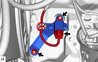
(b) Disengage the clamp.
(c) Remove the 2 nuts and acceleration sensor assembly LH.
NOTICE:
- Avoid any impact to the acceleration sensor assembly LH.
- Do not drop the acceleration sensor assembly LH. If it is dropped, replace it with a new one.
13. REMOVE ACCELERATION SENSOR ASSEMBLY RH (for RH Side)
| (a) Disconnect the connector from the acceleration sensor assembly RH. |
|
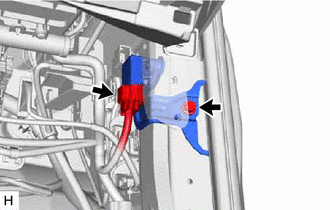
(b) Remove the bolt and acceleration sensor assembly RH.
NOTICE:
- Avoid any impact to the acceleration sensor assembly RH.
- Do not drop the acceleration sensor assembly RH. If it is dropped, replace it with a new one.
READ NEXT:
 Inspection
INSPECTION PROCEDURE 1. INSPECT ACCELERATION SENSOR ASSEMBLY (a) Connect 3 1.5 V dry cell batteries in series. (b) Connect a positive (+) lead from the batteries to terminal 3 and a negative (-) lead
Installation
INSTALLATION PROCEDURE 1. INSTALL ACCELERATION SENSOR ASSEMBLY LH (for LH Side) (a) Install the acceleration sensor assembly LH with the 2 nuts. Torque: 13 N·m {133 kgf·cm, 10 ft·lbf} NOTICE:
Relay
On-vehicle InspectionON-VEHICLE INSPECTION PROCEDURE 1. INSPECT AVS RELAY (a) Measure the resistance according to the value(s) in the table below. Standard Resistance: Tester Connection Cond
SEE MORE:
On-vehicle Inspection
ON-VEHICLE INSPECTION PROCEDURE 1. SECURE VEHICLE (a) Fully apply the parking brake and chock a wheel. CAUTION:
Make sure to apply the parking brake and chock a wheel before performing this procedure.
If the vehicle is not secure and the shift lever is moved to N, the vehicle may suddenly move,
Rear Power Window Switch
ComponentsCOMPONENTS ILLUSTRATION *1 REAR POWER WINDOW REGULATOR SWITCH ASSEMBLY *2 REAR POWER WINDOW REGULATOR SWITCH ASSEMBLY WITH REAR DOOR UPPER ARMREST BASE PANEL RemovalREMOVAL CAUTION / NOTICE / HINT HINT:
Use the same procedure for the RH side and LH side.
The following p
