Lexus ES: Components
Lexus ES (XZ10) Service Manual / Suspension / Rear Suspension / Rear Stabilizer Bar (for 2wd) / Components
COMPONENTS
ILLUSTRATION
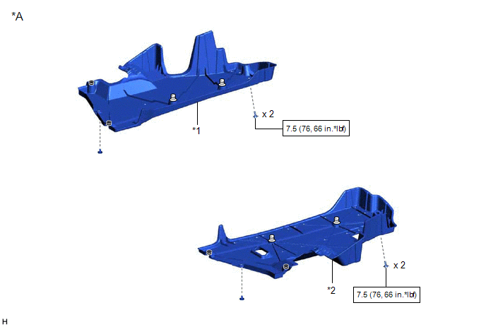
| *A | for Gasoline Model | - | - |
| *1 | NO. 1 FLOOR UNDER COVER | *2 | NO. 2 FLOOR UNDER COVER |
.png) | N*m (kgf*cm, ft.*lbf): Specified torque | - | - |
ILLUSTRATION
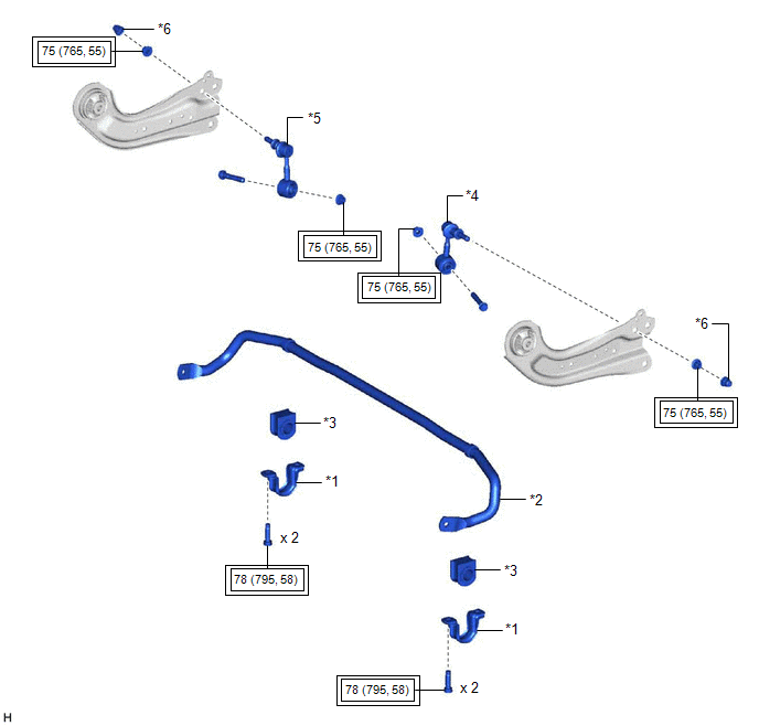
| *1 | REAR NO. 1 STABILIZER BAR BRACKET | *2 | REAR STABILIZER BAR |
| *3 | REAR STABILIZER BUSHING | *4 | REAR STABILIZER LINK ASSEMBLY LH |
| *5 | REAR STABILIZER LINK ASSEMBLY RH | *6 | CAP |
.png) | Tightening torque for "Major areas involving basic vehicle performance such as moving/turning/stopping": N*m (kgf*cm, ft.*lbf) | - | - |
READ NEXT:
 Removal
REMOVAL CAUTION / NOTICE / HINT The necessary procedures (adjustment, calibration, initialization, or registration) that must be performed after parts are removed and installed, or replaced during rea
Inspection
INSPECTION PROCEDURE 1. INSPECT REAR STABILIZER LINK ASSEMBLY (a) Inspect the turning torque of the ball joint. (1) Secure the rear stabilizer link assembly in a vise using aluminum plates. NOTICE:
Installation
INSTALLATION PROCEDURE 1. INSTALL REAR STABILIZER BUSHING (a) Install the 2 rear stabilizer bushings to the rear stabilizer bar. NOTICE: Be sure to install the rear stabilizer bushings so that each cu
SEE MORE:
Removal
REMOVAL CAUTION / NOTICE / HINT The necessary procedures (adjustment, calibration, initialization or registration) that must be performed after parts are removed and installed, or replaced during starter assembly removal/installation are shown below. Necessary Procedures After Parts Removed/Installe
Components
COMPONENTS ILLUSTRATION *1 CENTRAL GATEWAY ECU (NETWORK GATEWAY ECU) *2 ECU INTEGRATION BOX RH *3 GLOVE COMPARTMENT DOOR ASSEMBLY - -
© 2016-2026 Copyright www.lexguide.net
