Lexus ES: Components
COMPONENTS
ILLUSTRATION
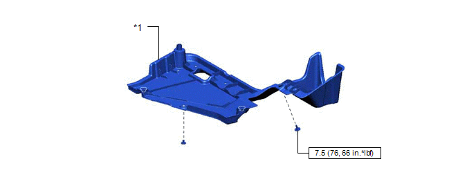
| *1 | NO. 2 FLOOR UNDER COVER | - | - |
.png) | N*m (kgf*cm, ft.*lbf): Specified torque | - | - |
ILLUSTRATION
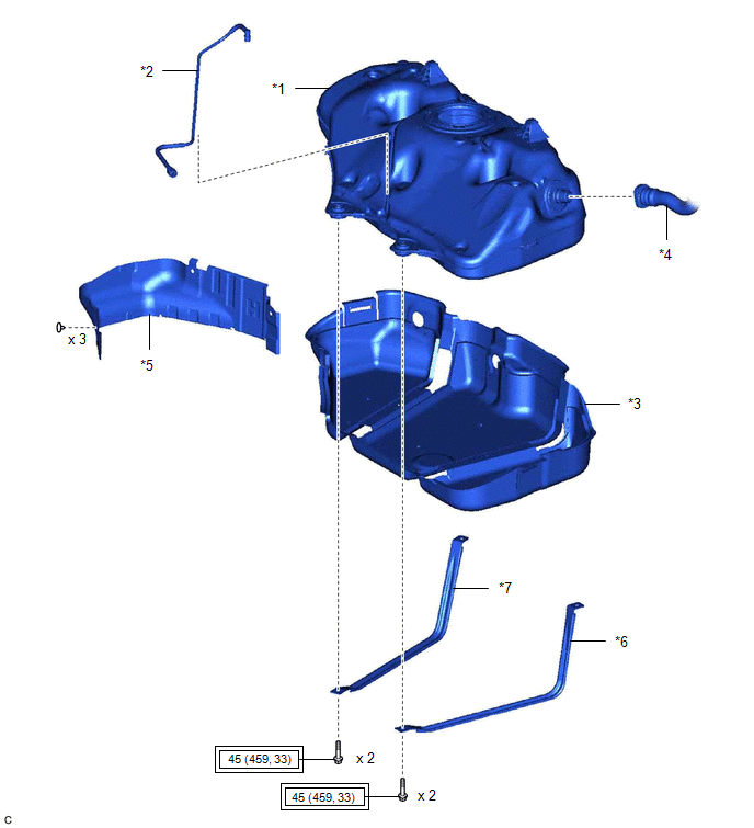
| *1 | FUEL TANK ASSEMBLY | *2 | FUEL TANK MAIN TUBE SUB-ASSEMBLY |
| *3 | NO. 1 FUEL TANK PROTECTOR SUB-ASSEMBLY | *4 | FUEL TANK TO FILLER PIPE HOSE |
| *5 | NO. 1 FUEL TANK PROTECTOR | *6 | NO. 1 FUEL TANK BAND SUB-ASSEMBLY LH |
| *7 | NO. 1 FUEL TANK BAND SUB-ASSEMBLY RH | - | - |
.png) | Tightening torque for "Major areas involving basic vehicle performance such as moving/turning/stopping": N*m (kgf*cm, ft.*lbf) | - | - |
READ NEXT:
 Removal
REMOVAL CAUTION / NOTICE / HINT The necessary procedures (adjustment, calibration, initialization or registration) that must be performed after parts are removed and installed, or replaced during fuel
Installation
INSTALLATION PROCEDURE 1. INSTALL NO. 1 FUEL TANK PROTECTOR SUB-ASSEMBLY (a) Engage the 2 claws to install the No. 1 fuel tank protector sub-assembly to the fuel tank assembly. 2. INSTALL FUEL TANK MA
SEE MORE:
Removal
REMOVAL CAUTION / NOTICE / HINT The necessary procedures (adjustment, calibration, initialization, or registration) that must be performed after parts are removed and installed, or replaced during rear shock absorber assembly removal/installation are shown below. Necessary Procedures After Parts Rem
Problem Symptoms Table
PROBLEM SYMPTOMS TABLE HINT:
Use the table below to help determine the cause of problem symptoms. If multiple suspected areas are listed, the potential causes of the symptoms are listed in order of probability in the "Suspected Area" column of the table. Check each symptom by checking the suspect
© 2016-2026 Copyright www.lexguide.net
