Lexus ES: Installation
INSTALLATION
PROCEDURE
1. INSTALL REAR STABILIZER BUSHING
(a) Install the 2 rear stabilizer bushings to the rear stabilizer bar.
NOTICE:
Be sure to install the rear stabilizer bushings so that each cutout faces the front of the vehicle.
2. INSTALL REAR NO. 1 STABILIZER BAR BRACKET
(a) Install the 2 rear No. 1 stabilizer bar brackets to the 2 rear stabilizer bushings.
NOTICE:
Be sure to install the rear No. 1 stabilizer bar brackets so that each arrow mark faces the front of the vehicle.
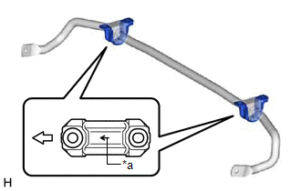
| *a | Arrow Mark |
.png) | Front of the Vehicle |
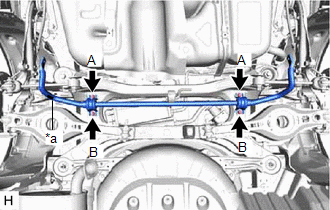
3. INSTALL REAR STABILIZER BAR
| (a) Install the rear stabilizer bar, 2 rear No. 1 stabilizer bar brackets and 2 rear stabilizer bushings to the rear suspension member sub-assembly with the 4 bolts. Torque: 78 N·m {795 kgf·cm, 58 ft·lbf} NOTICE:
|
|
4. STABILIZE SUSPENSION
Click here .gif)
5. INSTALL REAR STABILIZER LINK ASSEMBLY LH
| (a) Install the rear stabilizer link assembly LH with the nut (A). Torque: 75 N·m {765 kgf·cm, 55 ft·lbf} HINT: If the ball joint turns together with the nut, use a 6 mm hexagon socket wrench to hold the stud bolt. |
|
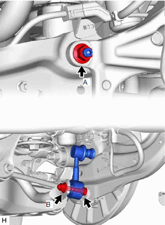
(b) Install the rear stabilizer link assembly LH with the bolt and nut (B).
Torque:
75 N·m {765 kgf·cm, 55 ft·lbf}
(c) Install the cap to the rear stabilizer link assembly LH.
6. INSTALL REAR STABILIZER LINK ASSEMBLY RH
HINT:
Perform the same procedure as for the LH side.
7. INSTALL CENTER EXHAUST PIPE ASSEMBLY
for 2GR-FKS: Click here
for A25A-FXS: Click here
8. INSTALL NO. 1 FLOOR UNDER COVER (for Gasoline Model)
| (a) Install the No. 1 floor under cover with the 2 grommets (B) and 2 clips (C). |
|
.png)
(b) Install the 2 bolts and clip (A).
Torque:
Bolt :
7.5 N·m {76 kgf·cm, 66 in·lbf}
9. INSTALL NO. 2 FLOOR UNDER COVER (for Gasoline Model)
| (a) Install the No. 2 floor under cover with the 2 grommets (B) and 2 clips (C). |
|
.png)
(b) Install the 2 bolts and clip (A).
Torque:
Bolt :
7.5 N·m {76 kgf·cm, 66 in·lbf}
10. INSTALL REAR WHEEL
Click here
11. INSPECT FOR EXHAUST GAS LEAK
for 2GR-FKS: Click here
for A25A-FXS: Click here
READ NEXT:
 Components
COMPONENTS ILLUSTRATION *1 REAR LOWER STABILIZER BRACKET *2 REAR NO. 1 STABILIZER BAR BRACKET *3 REAR STABILIZER BAR *4 REAR STABILIZER BUSHING *5 REAR STABILIZER LINK ASSEMB
Removal
REMOVAL CAUTION / NOTICE / HINT The necessary procedures (adjustment, calibration, initialization, or registration) that must be performed after parts are removed and installed, or replaced during rea
SEE MORE:
ECM Power Source Circuit
DESCRIPTION When the engine switch is turned on (IG), the battery voltage is applied to the IGSW terminal of the ECM. The output signal from the MREL terminal of the ECM causes a current to flow to the coil of the EFI-MAIN NO. 1 relay, closing the contacts and supplying power to terminals +B and +B2
Indicator (Red) Circuit Short to Ground (B157011,B157013)
DESCRIPTION This DTC is stored when the DCM (telematics transceiver) detects an open or short in the manual (SOS) switch red indicator circuit of the manual (SOS) switch. The manual (SOS) switch red indicator illuminates for 2 seconds and goes off when the engine switch is turned on (IG). If a malfu
