Lexus ES: Removal
REMOVAL
CAUTION / NOTICE / HINT
The necessary procedures (adjustment, calibration, initialization, or registration) that must be performed after parts are removed and installed, or replaced during air fuel ratio sensor removal/installation are shown below.
Necessary Procedures After Parts Removed/Installed/Replaced| Replaced Part or Performed Procedure | Necessary Procedure | Effect/Inoperative Function when Necessary Procedure not Performed | Link |
|---|---|---|---|
| Inspection after repair |
| |
.gif)
PROCEDURE
1. REMOVE AIR FUEL RATIO SENSOR
CAUTION:
To prevent burns, do not touch the engine, exhaust pipe or other high temperature components while the engine is hot.
.png)
| (a) Disengage the wire harness clamp. |
|
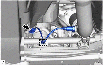
(b) Disconnect the air fuel ratio sensor connector.
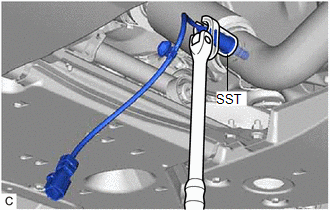
| (c) Using SST, remove the air fuel ratio sensor from the front exhaust pipe assembly (TWC: Rear Catalyst). SST: 09224-00012 NOTICE: If the air fuel ratio sensor has been struck or dropped, replace it. |
|
READ NEXT:
 Inspection
INSPECTION PROCEDURE 1. INSPECT AIR FUEL RATIO SENSOR (a) Measure the resistance according to the value(s) in the table below. Standard Resistance: Tester Connection Condition Specified Con
Installation
INSTALLATION PROCEDURE 1. INSTALL AIR FUEL RATIO SENSOR HINT: Perform "Inspection After Repair" after replacing the air fuel ratio sensor. Click here (a) Using SST, install the air fuel ratio
SEE MORE:
Torque Sensor Zero Point Adjustment Undone (C1515)
DESCRIPTION This DTC does not indicate a malfunction. The power steering ECU (rack and pinion power steering gear assembly) stores this DTC when it determines that torque sensor zero point calibration has not been performed. When the IG terminal voltage is below 8 V, torque sensor zero point calibra
Diagnosis System
DIAGNOSIS SYSTEM PARKING ASSIST MONITOR DIAGNOSIS SYSTEM (a) For panoramic view monitor system diagnosis, signals received by the parking assist ECU can be checked, and the panoramic view monitor system can be calibrated, adjusted and checked using the multi-display assembly. NOTICE: Depending on th
