Lexus ES: Components
Lexus ES (XZ10) Service Manual / Steering / Steering Column / Tilt And Telescopic Manual Switch / Components
COMPONENTS
ILLUSTRATION
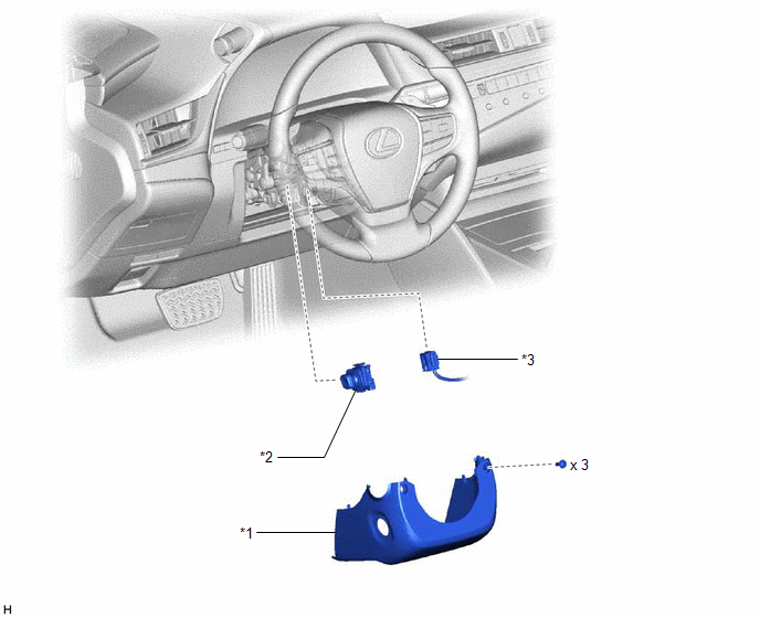
| *1 | LOWER STEERING COLUMN COVER SUB-ASSEMBLY | *2 | TILT AND TELESCOPIC SWITCH |
| *3 | SPIRAL CABLE CONNECTOR | - | - |
READ NEXT:
 Removal
REMOVAL CAUTION / NOTICE / HINT The necessary procedures (adjustment, calibration, initialization or registration) that must be performed after parts are removed and installed, or replaced during tilt
Inspection
INSPECTION PROCEDURE 1. INSPECT TILT AND TELESCOPIC SWITCH (a) Remove the tilt and telescopic switch. Click here (b) Measure the resistance according to the value(s) in the table below. Standar
Installation
INSTALLATION PROCEDURE 1. INSTALL TILT AND TELESCOPIC SWITCH (a) Engage the claw to install the tilt and telescopic switch. (b) Connect the tilt and telescopic connector to the tilt and telescopic swi
SEE MORE:
Noise Occurs or Sound Skips when Portable Player Plays
CAUTION / NOTICE / HINT HINT:
Perform this check with the portable player volume set at an appropriate level.
Make sure that there are no obstructions between the portable player and radio receiver assembly that may block signals, and that the portable player and radio receiver assembly are not
Open or Short in Steering Angle Sensor +B (C1625)
DESCRIPTION
This DTC is stored if the parking assist ECU receives a signal via CAN communication from the steering sensor that indicates a power supply system problem.
This DTC is stored if the rear television camera assembly receives a signal via CAN communication from the steering sensor that
© 2016-2026 Copyright www.lexguide.net
