Lexus ES: Removal
REMOVAL
CAUTION / NOTICE / HINT
The necessary procedures (adjustment, calibration, initialization or registration) that must be performed after parts are removed and installed, or replaced during tilt and telescopic switch removal/installation are shown below.
Necessary Procedures After Parts Removed/Installed/Replaced (for Gasoline Model)| Replaced Part or Performed Procedure | Necessary Procedure | Effect/Inoperative Function when Necessary Procedure not Performed | Link |
|---|---|---|---|
|
*: When performing learning using the Techstream.
Click here | |||
| Disconnect cable from negative auxiliary battery terminal | Perform steering sensor zero point calibration | Lane Control System | |
| Pre-collision System | |||
| Parking Support Brake System* | |||
| Lighting System | |||
| Memorize steering angle neutral point | Parking Assist Monitor System | | |
| Panoramic View Monitor System | | ||
| Initialize power trunk lid system | Power Trunk Lid System | | |
| Replaced Part or Performed Procedure | Necessary Procedure | Effect/Inoperative Function when Necessary Procedure not Performed | Link |
|---|---|---|---|
|
*: When performing learning using the Techstream.
Click here | |||
| Disconnect cable from negative auxiliary battery terminal | Perform steering sensor zero point calibration | Lane Control System | |
| Pre-collision System | |||
| Parking Support Brake System* | |||
| Lighting System | |||
| Memorize steering angle neutral point | Parking Assist Monitor System | | |
| Panoramic View Monitor System | | ||
| Initialize power trunk lid system | Power Trunk Lid System | | |
NOTICE:
for Gasoline Model:- After the engine switch is turned off, the radio receiver assembly records various types of memory and settings. As a result, after turning the engine switch off, make sure to wait at least 85 seconds before disconnecting the cable from the negative (-) battery terminal. (for Audio and Visual System)
- After the engine switch is turned off, the radio receiver assembly records various types of memory and settings. As a result, after turning the engine switch off, make sure to wait at least 85 seconds before disconnecting the cable from the negative (-) battery terminal. (for Navigation System)
- After the power switch is turned off, the radio receiver assembly records various types of memory and settings. As a result, after turning the power switch off, make sure to wait at least 85 seconds before disconnecting the cable from the negative (-) auxiliary battery terminal. (for Audio and Visual System)
- After the power switch is turned off, the radio receiver assembly records various types of memory and settings. As a result, after turning the power switch off, make sure to wait at least 85 seconds before disconnecting the cable from the negative (-) auxiliary battery terminal. (for Navigation System)
PROCEDURE
1. CHANGE POWER TILT AND POWER TELESCOPIC STEERING COLUMN SYSTEM SETTINGS
Click here .gif)
2. REMOVE LOWER STEERING COLUMN COVER SUB-ASSEMBLY
Click here
3. DISCONNECT CABLE FROM NEGATIVE AUXILIARY BATTERY TERMINAL
for Gasoline Model: Click here
for HV Model: Click here
CAUTION:
Wait at least 90 seconds after disconnecting the cable from the negative (-) auxiliary battery terminal to disable the SRS system.
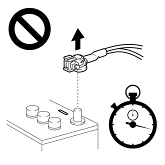
NOTICE:
When disconnecting the cable, some systems need to be initialized after the cable is reconnected.
Click here
4. REMOVE TILT AND TELESCOPIC SWITCH
| (a) Disconnect the spiral cable connector from the spiral cable sub-assembly. |
|
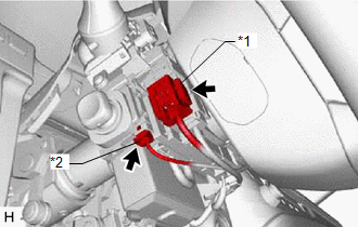
(b) Disconnect the tilt and telescopic connector from the tilt and telescopic switch.
(c) Disengage the claw and pull out the tilt and telescopic switch.

| *a | Claw |
.png) | Pull out in this direction |
READ NEXT:
 Inspection
INSPECTION PROCEDURE 1. INSPECT TILT AND TELESCOPIC SWITCH (a) Remove the tilt and telescopic switch. Click here (b) Measure the resistance according to the value(s) in the table below. Standar
Installation
INSTALLATION PROCEDURE 1. INSTALL TILT AND TELESCOPIC SWITCH (a) Engage the claw to install the tilt and telescopic switch. (b) Connect the tilt and telescopic connector to the tilt and telescopic swi
Installation
INSTALLATION PROCEDURE 1. INSTALL TILT AND TELESCOPIC SWITCH (a) Engage the claw to install the tilt and telescopic switch. (b) Connect the tilt and telescopic connector to the tilt and telescopic swi
SEE MORE:
Freeze Frame Data
FREEZE FRAME DATA FREEZE FRAME DATA (a) The absorber control ECU stores system condition information as freeze frame data the moment a DTC is stored. The Freeze Frame Data can be displayed using the Techstream. (b) Freeze frame data when a DTC is stored. (1) Freeze frame data is stored the moment a
Starter Signal Circuit
DESCRIPTION While the engine is being cranked, current flows from terminal STAR of the certification ECU (smart key ECU assembly) to the park/neutral position switch assembly and to terminal STA of the ECM (STA signal). WIRING DIAGRAM Refer to DTC P061512. Click here CAUTION / NOTICE / HINT NOTIC
