Lexus ES: Components
COMPONENTS
ILLUSTRATION
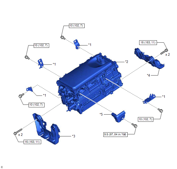
| *1 | WIRE HARNESS CLAMP BRACKET | *2 | INVERTER WITH CONVERTER ASSEMBLY |
| *3 | NO. 1 INVERTER BRACKET | *4 | NO. 2 INVERTER BRACKET |
| *5 | INVERTER PROTECTOR | - | - |
.png) | N*m (kgf*cm, ft.*lbf): Specified torque | - | - |
ILLUSTRATION
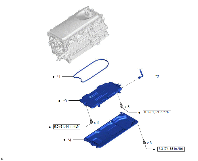
| *1 | O-RING | *2 | CONNECTOR |
| *3 | HV CONVERTER KIT | *4 | CONVERTER COVER |
| | N*m (kgf*cm, ft.*lbf): Specified torque | ● | Non-reusable part |
READ NEXT:
 Removal
REMOVAL CAUTION / NOTICE / HINT The necessary procedures (adjustment, calibration, initialization or registration) that must be performed after parts are removed and installed, or replaced during HV c
Installation
INSTALLATION CAUTION / NOTICE / HINT NOTICE: Do not cross-thread the bolts when installing them. PROCEDURE 1. HOW TO PREVENT STATIC ELECTRICITY SST: 09890-47010 NOTICE:
Static electricity should be
SEE MORE:
How To Proceed With Troubleshooting
CAUTION / NOTICE / HINT HINT:
Use the following procedure to troubleshoot the wiper and washer system.
*: Use the Techstream.
PROCEDURE 1. VEHICLE BROUGHT TO WORKSHOP
NEXT 2. CUSTOMER PROBLEM ANALYSIS HINT:
In troubleshooting, confirm that the proble
Parts Location
PARTS LOCATION ILLUSTRATION *1 FRONT CORNER ULTRASONIC SENSOR RH *2 FRONT CENTER ULTRASONIC SENSOR RH *3 FRONT CENTER ULTRASONIC SENSOR LH *4 FRONT CORNER ULTRASONIC SENSOR LH *5 REAR CORNER ULTRASONIC SENSOR RH *6 REAR CENTER ULTRASONIC SENSOR RH *7 REAR CENTER U
© 2016-2026 Copyright www.lexguide.net
