Lexus ES: Installation
INSTALLATION
CAUTION / NOTICE / HINT
NOTICE:
Do not cross-thread the bolts when installing them.
PROCEDURE
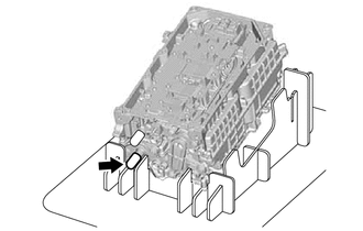
1. HOW TO PREVENT STATIC ELECTRICITY
SST: 09890-47010
NOTICE:
- Static electricity should be eliminated when removing/installing the inverter with converter assembly.
- Do not touch the electronic components of a circuit board.
- Keep clothes away from electronic components.
- Place the inverter with converter assembly and any removed electronic components on SST (antistatic mat).
| (a) Wear an antistatic wrist strap. |
|
.png)
(b) Connect the ground clip of the antistatic mat securely to a ground point provided in the workshop or on a workbench (anchor bolt).
HINT:
If the ground clip cable is too short, use an extension cable.
(c) Connect the ground clip of the antistatic wrist strap securely to the specified point of the antistatic mat.
(d) When handling internal components of the inverter with converter assembly, use only antistatic gloves or bare hands to prevent damage from static electricity or the entry of foreign matter.
2. INSTALL HV CONVERTER KIT
CAUTION:
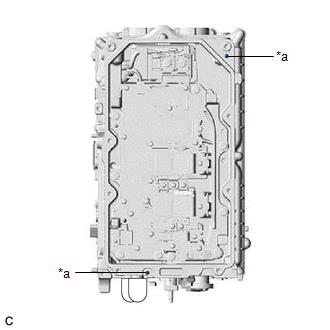
- As there is a coolant passage underneath the HV converter kit, be careful not to spill any coolant (for inverter) into the filter condenser or the holes around the edge of the inverter with converter assembly.
- If any coolant (for inverter) spills into the filter condenser or the holes around the edge of the inverter with converter assembly, do not reuse the inverter with converter assembly.
- If any coolant (for inverter) spills onto any area other than the specified areas, remove it with a clean piece of cloth.
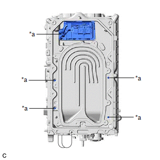
| *a | Do Not Allow Coolant (for Inverter) to Enter |
NOTICE:
- Be careful not to touch any part of the HV converter kit other than the specified areas.
- Do not allow any moisture to come into contact with the circuit board.
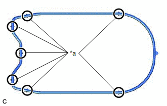
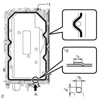
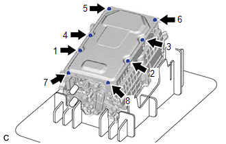
| (a) Install a new O-ring to the inverter with converter assembly and then press it at the 7 areas shown in the illustration to ensure it is installed securely. NOTICE: Make sure that the O-ring is free of foreign matter. HINT: The O-ring is symmetrical. |
|
(b) While holding the corners of a new HV converter kit, align it with the guide pins of the inverter with converter assembly and temporarily install it.
NOTICE:
Make sure that the sealing surfaces and contact surfaces are free of foreign matter.
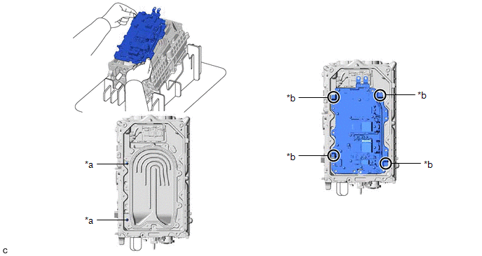
| *a | Guide Pin | *b | Hold Here |
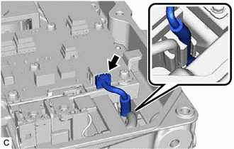
| (c) Connect the HV converter kit connector. NOTICE:
|
|
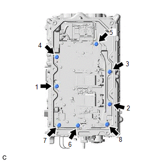
| (d) Temporarily install new 8 bolts evenly in several steps in the order shown in the illustration, and then tighten them to the specified torque. Torque: 6.0 N·m {61 kgf·cm, 53 in·lbf} |
|
| (e) Temporarily install new 3 bolts evenly in several steps in the order shown in the illustration, and then tighten them to the specified torque. Torque: 5.0 N·m {51 kgf·cm, 44 in·lbf} |
|
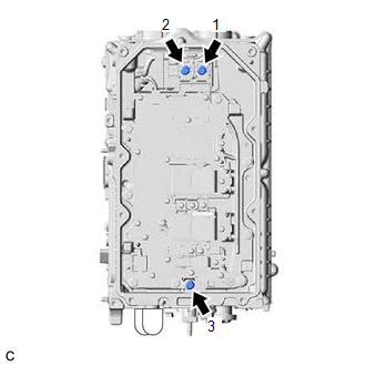
(f) Check the torque of the 11 bolts in the order shown in the illustration.
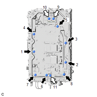
.png) | Bolt (A) |
.png) | Bolt (B) |
Torque:
Bolt (A) :
6.0 N·m {61 kgf·cm, 53 in·lbf}
Bolt (B) :
5.0 N·m {51 kgf·cm, 44 in·lbf}
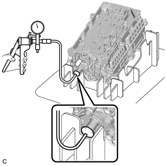
3. CHECK FOR AIR LEAK
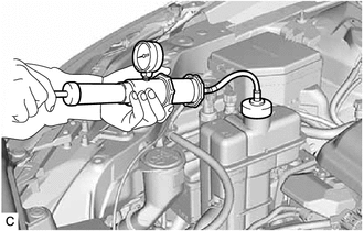
| (a) Remove the cap from the black colored coolant pipe. |
|
| (b) Using a vacuum pump, apply a vacuum of 50 kPa (375 mmHg) and check vacuum can be maintained. Standard: The vacuum pressure does not decrease for at least 30 seconds. NOTICE: If the vacuum pressure decreases, check for a leak between the vacuum pump and coolant pipe. If a leak is not found, remove the HV converter kit and check the installation condition of the O-ring. |
|
4. INSTALL CONVERTER COVER
NOTICE:
- Do not touch the circuit board.
- Do not allow any foreign matter or water to enter the inverter with converter assembly.
- Do not touch or allow grease or oil to contact the sealing surfaces of the inverter with converter assembly.
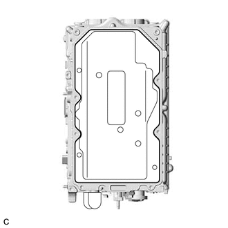
(a) Clean the seal packing removal cover.
| (b) Set the seal packing removal cover on the inverter with converter assembly. |
|
| (c) Apply seal packing (diameter: 3.0 mm (0.118 in.)) in a continuous line to the locations shown in the illustration. Seal Packing: Toyota Genuine Seal Packing 1207F NOTICE:
|
|
(d) Remove the seal packing removal cover.
NOTICE:
Slowly remove the seal packing removal cover without touching the seal packing surface.
| (e) Align a new converter cover with the guide pins of the inverter with converter assembly and temporarily install it. NOTICE:
|
|
| (f) Temporarily install new 8 bolts evenly in several steps in the order shown in the illustration, and then tighten them to the specified torque. Torque: 7.3 N·m {74 kgf·cm, 65 in·lbf} |
|
(g) Check the torque of the 8 bolts in the order shown in the illustration.
Torque:
7.3 N·m {74 kgf·cm, 65 in·lbf}
NOTICE:
Make sure that the bolts are securely contacting the converter cover.
5. INSTALL INVERTER PROTECTOR
Click here .gif)
6. INSTALL WIRE HARNESS CLAMP BRACKET
Click here
7. INSTALL NO. 2 INVERTER BRACKET
Click here
8. INSTALL NO. 1 INVERTER BRACKET
Click here
9. INSTALL INVERTER WITH CONVERTER ASSEMBLY
Click here
10. INSPECT FOR COOLANT LEAK (for Inverter)
CAUTION:
To avoid the danger of being burned, do not remove the reserve tank cap while the coolant (for inverter) is still hot. Pressurized, hot coolant (for inverter) and steam may be released and cause serious burns.
(a) Remove the reserve tank cap from the inverter reserve tank assembly.
(b) Add coolant to the FULL line of the inverter reserve tank assembly.
| (c) Install a radiator cap tester to the inverter reserve tank assembly. |
|
(d) Pump the radiator cap tester to 122 kPa (1.2 kgf/ cm2, 18 psi), and then check that the pressure does not drop.
HINT:
If the pressure drops, check the hoses, radiator assembly, inverter water pump assembly, hybrid vehicle transaxle assembly, and inverter with converter assembly for leaks.
(e) Reinstall the reserve tank cap to the inverter reserve tank assembly.
11. OPERATION CHECK
HINT:
After the repair, perform the operation checks as follows. Then check for DTCs again.
(a) Operation check 1
(1) Connect the Techstream to the DLC3.
(2) Turn the power switch on (IG), turn the Techstream on and clear the DTCs.
(3) Turn the power switch on (READY).
(4) Warm up the engine with the shift lever in P and the A/C turned off until the engine stops.
HINT:
The engine will stop automatically when it is warmed up.
(5) Depress the accelerator pedal with the shift lever in P to start the engine.
(6) As soon as the engine starts, release the accelerator pedal and wait until the engine stops.
(7) Move the shift lever to D and creep the vehicle forward 5 m (16.4 ft.) with the engine stopped and without depressing the accelerator pedal.
NOTICE:
Confirm the safety of the surrounding area before moving the vehicle.
(8) Move the shift lever to R and creep the vehicle backward 5 m (16.4 ft.) with the engine stopped and without depressing the accelerator pedal.
NOTICE:
Confirm the safety of the surrounding area before moving the vehicle.
(b) Operation check 2
HINT:
The current at the AMD terminal cannot be measured directly because of space limitations. Measure the current flowing at the auxiliary battery instead.
| (1) Connect the AC/DC 400 A probe of the tester to the positive (+) auxiliary battery cable. |
|
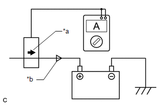
(2) Turn the power switch on (READY) and leave the vehicle as it is until the electric current flowing to the auxiliary battery becomes 10 A or less.
| (3) Change the orientation of the AC/DC 400 A probe. |
|
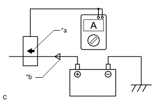
(4) Measure the current flowing from the auxiliary battery with the power switch on (READY), the headlight position switch and blower motor switch in the HI position, and the rear window defogger turned on.
Standard Current:
| Item | Condition | Specified Condition |
|---|---|---|
| Current flowing from auxiliary battery | Power switch on (READY) (Headlight position switch and blower motor switch in HI position, and rear window defogger on) | 0 A or less (No current from auxiliary battery) |
(5) Turn the power switch off.
READ NEXT:
 Components
COMPONENTS ILLUSTRATION *1 BATTERY SERVICE HOLE COVER *2 SERVICE PLUG GRIP ILLUSTRATION *1 CONNECTOR COVER ASSEMBLY *2 ENGINE ROOM MAIN WIRE Tightening torque for "Major
Removal
REMOVAL CAUTION / NOTICE / HINT The necessary procedures (adjustment, calibration, initialization or registration) that must be performed after parts are removed and installed, or replaced during HV f
SEE MORE:
Installation
INSTALLATION PROCEDURE 1. INSTALL AIR FUEL RATIO SENSOR HINT: Perform "Inspection After Repair" after replacing the air fuel ratio sensor. Click here (a) Using SST, install the air fuel ratio sensor to the front exhaust pipe assembly (TWC: Rear Catalyst). SST: 09224-00012 Torque: Specified
Pressure Control Solenoid "G" Circuit Short to Battery (P280712)
DESCRIPTION Changing gears is performed by the ECM turning the solenoid (SL1, SL2, SL3, SL4, SL5 and SL6) valves on and off. If an open or short occurs in any of the solenoid valve circuits, the ECM controls the remaining normal solenoid valves to allow the vehicle to be driven. If all of the soleno
