Lexus ES: Removal
REMOVAL
CAUTION / NOTICE / HINT
The necessary procedures (adjustment, calibration, initialization or registration) that must be performed after parts are removed and installed, or replaced during HV converter kit removal/installation are shown below.
Necessary Procedures After Parts Removed/Installed/Replaced| Replaced Part or Performed Procedure | Necessary Procedure | Effect/Inoperative Function when Necessary Procedure not Performed | Link |
|---|---|---|---|
|
*: When performing learning using the Techstream.
Click here | |||
| Auxiliary battery terminal is disconnected/reconnected | Perform steering sensor zero point calibration | Lane Control System | |
| Pre-collision system | |||
| Parking Support Brake System* | |||
| Lighting system | |||
| Memorize steering angle neutral point | Parking assist monitor system | | |
| Panoramic view monitor system | | ||
| Initialize power trunk lid system | Power Trunk Lid System | | |
| Replacement of inverter with converter assembly | Resolver learning |
| |
| Replacement of ECM | Perform Vehicle Identification Number (VIN) registration | MIL illuminates | |
CAUTION:
-
Orange wire harnesses and connectors indicate high-voltage circuits. To prevent electric shock, always follow the procedure described in the repair manual.
.png)
Click here
.gif)
-
To prevent electric shock, wear insulated gloves when working on wire harnesses and components of the high voltage system.
.png)
NOTICE:
- After the power switch is turned off, the radio receiver assembly records various types of memory and settings. As a result, after turning the power switch off, make sure to wait at least 85 seconds before disconnecting the cable from the negative (-) auxiliary battery terminal. (for Audio and Visual System)
- After the power switch is turned off, the radio receiver assembly records various types of memory and settings. As a result, after turning the power switch off, make sure to wait at least 85 seconds before disconnecting the cable from the negative (-) auxiliary battery terminal. (for Navigation System)
-
If metal shavings are created when bolts are removed from the inverter with converter assembly, remove them using tape or equivalent.
- Use non-residue type tape.
PROCEDURE
1. REMOVE INVERTER WITH CONVERTER ASSEMBLY
Click here
2. REMOVE NO. 1 INVERTER BRACKET
Click here
3. REMOVE NO. 2 INVERTER BRACKET
Click here
4. REMOVE WIRE HARNESS CLAMP BRACKET
Click here
5. REMOVE INVERTER PROTECTOR
Click here
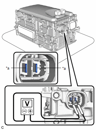
6. VERIFY THAT VOLTAGE OF INVERTER WITH CONVERTER IS 0 V
CAUTION:
Be sure to wear insulated gloves.
NOTICE:
Do not allow any foreign matter or water to enter the inverter with converter assembly.
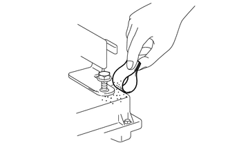
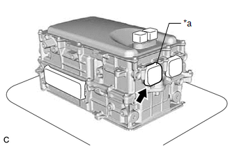
| (a) Remove the protective tape from the HV floor under wire opening. |
|
| (b) Using a voltmeter, measure the voltage between the high voltage cable connector terminals. Standard Voltage: 0 V HINT:
|
|
(c) Apply protective tape to the area that was exposed.
NOTICE:
Use non-residue type tape.
7. CLEAN INVERTER WITH CONVERTER ASSEMBLY
(a) Using a piece of cloth, clean the outside of the inverter with converter assembly and around the bolts.
NOTICE:
To prevent foreign matter from entering the inverter with converter assembly, make sure that the protective tape is not partially removed.
8. HOW TO PREVENT STATIC ELECTRICITY
SST: 09890-47010
NOTICE:
- Static electricity should be eliminated when removing/installing the inverter with converter assembly.
- Do not touch the electronic components of a circuit board.
- Keep clothes away from electronic components.
- Place the inverter with converter assembly and any removed electronic components on SST (antistatic mat).
| (a) Wear an antistatic wrist strap. |
|
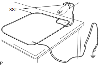
(b) Connect the ground clip of the antistatic mat securely to a ground point provided in the workshop or on a workbench (anchor bolt).
HINT:
If the ground clip cable is too short, use an extension cable.
(c) Connect the ground clip of the antistatic wrist strap securely to the specified point of the antistatic mat.
(d) When handling internal components of the inverter with converter assembly, use only antistatic gloves or bare hands to prevent damage from static electricity or the entry of foreign matter.
9. DRAIN COOLANT (for Inverter)
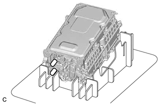
| (a) Place the inverter with converter assembly on a stand as shown in the illustration. NOTICE:
|
|
(b) Connect the ground clip of the antistatic wrist strap securely to the inverter with converter assembly.
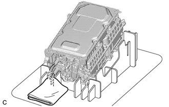
| (c) Remove the 2 caps from the coolant pipes and drain the coolant (for inverter). |
|
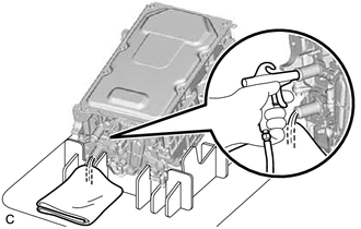
| (d) Blow compressed air into the inverter with converter assembly until most all of the coolant (for inverter) is blown out. NOTICE:
HINT:
(1) Install the 2 caps to the coolant pipes. |
|
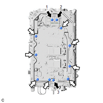
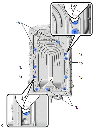
10. REMOVE CONVERTER COVER
| (a) Remove the 8 bolts. |
|
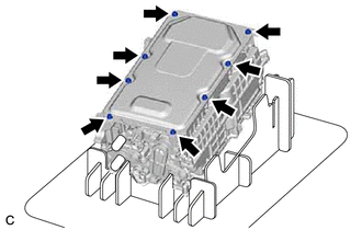
(b) Using a screwdriver with its tip wrapped with protective tape, remove the converter cover from the inverter with converter assembly.
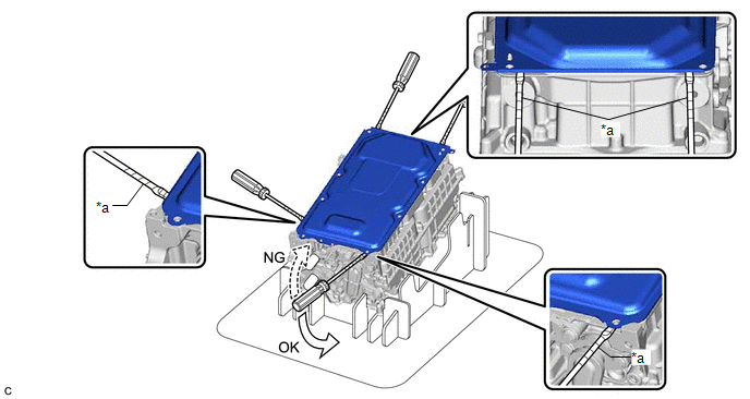
| *a | Protective Tape | - | - |
NOTICE:
- Do not damage the sealing surfaces of the inverter with converter assembly.
- Do not touch or allow grease or oil to contact the sealing surfaces of the inverter with converter assembly.
- Be careful not to damage the sealing surfaces of the inverter with converter assembly.
- To prevent internal components of the inverter with converter assembly from being damaged, do not insert the screwdriver excessively.
11. REMOVE SEAL PACKING FROM INVERTER WITH CONVERTER ASSEMBLY
NOTICE:
- Do not allow any removed seal packing to enter the inverter with converter assembly.
- Do not touch the circuit board.
- Do not allow any moisture to come into contact.
(a) Using a finger, remove any seal packing that has seeped into the inverter with converter assembly.
HINT:
Make sure to remove any seal packing which has seeped toward the inside of inverter with converter assembly before installing the seal packing removal cover, otherwise the seal packing may be pushed into the inverter with converter assembly.
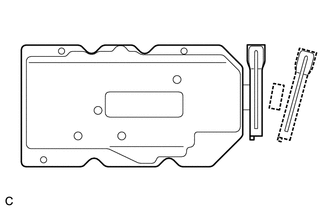
| (b) Break off the seal packing removal cover and scraper at each break off line. |
|
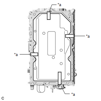
| (c) Set the seal packing removal cover on the inverter with converter assembly and secure it with tape. NOTICE: Make sure that the seal packing removal cover is in secure contact with the inside surface of the inverter with converter assembly without any gaps. |
|
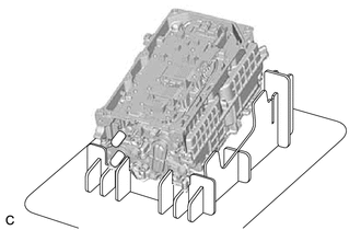
| (d) Place the inverter with converter assembly on its side on an antistatic mat as shown in the illustration. NOTICE:
|
|
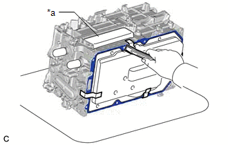
(e) Using a scraper, remove any remaining seal packing from the inverter with converter assembly.
NOTICE:
-
It is not necessary to remove small amounts of seal packing which are not easily scraped off.
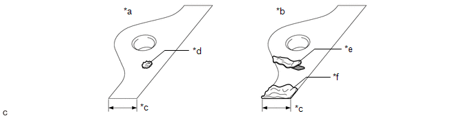
*a
Correct
*b
Incorrect
*c
Width of Sealing Surface
*d
Difficult to Remove Seal Packing
*e
Peeled Off Seal Packing
*f
Seal Packing Remaining on Full Width of Sealing Surface
-
Make sure to use the scraper supplied with the seal packing removal cover.
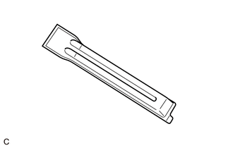
HINT:
Use the small end of the scraper to remove seal packing from small areas such as bolt holes.
(f) Remove the tape used to secure the seal packing removal cover and then remove any seal packing which was under the tape.
(g) Using a clean piece of cloth, clean the sealing surfaces of the inverter with converter assembly.
NOTICE:
- Do not use compressed air or a vacuum cleaner to clean the sealing surfaces of the inverter with converter assembly.
- Do not use non-residue solvent to clean the sealing surfaces of the inverter with converter assembly.
| (h) Remove the seal packing removal cover. NOTICE: Make sure that the inverter with converter assembly is oriented correctly, otherwise seal packing may enter the inverter with converter assembly when removing the seal packing removal cover. |
|
(i) Make sure that the inverter with converter assembly is free of foreign matter.
12. REMOVE HV CONVERTER KIT
NOTICE:
- Do not touch the circuit board.
- Do not allow any foreign matter or water to enter the inverter with converter assembly.
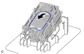
| (a) Place the inverter with converter assembly on a stand as shown in the illustration. NOTICE: Make sure that the inverter with converter assembly is oriented correctly. |
|
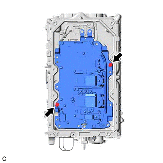
(b) Remove the 3 bolts (A) in the order shown in the illustration.
.png) | Bolt (A) |
.png) | Bolt (B) |
(c) Remove the 8 bolts (B).
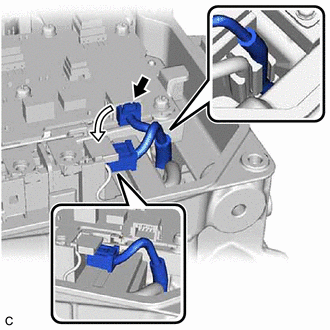
| (d) Disconnect the HV converter kit connector and set it as shown in the illustration. NOTICE: Make sure that the wire harness of the connector is engaged to the filter condenser. |
|
| (e) Install 2 HV converter kit installation bolts at the positions shown in the illustration and tighten them in several steps to separate the HV converter kit from the inverter with converter assembly. NOTICE:
|
|
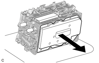
(f) Hold the corners of the HV converter kit and remove it as shown in the illustration.
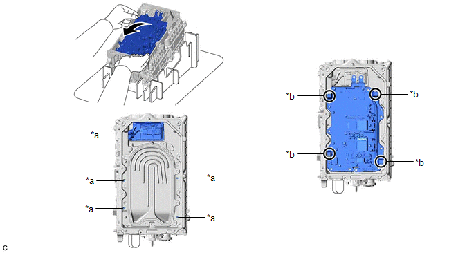
| *a | Do Not Allow Coolant (for Inverter) to Enter | *b | Hold Here |
| | Remove in this Direction | - | - |
CAUTION:
- As there is a coolant passage underneath the HV converter kit, be careful not to spill any coolant (for inverter) into the filter condenser or the holes around the edge of the inverter with converter assembly.
- If any coolant (for inverter) spills into the filter condenser or the holes around the edge of the inverter with converter assembly, do not reuse the inverter with converter assembly.
- If any coolant (for inverter) spills onto any area other than the specified areas, remove it with a clean piece of cloth.
| (g) Remove any metal shavings from the areas around the bolt holes and 2 positions where bolts were installed to separate the HV converter kit, using tape or equivalent. |
|
| (h) Using a clean scraper, lift the O-ring at the position shown in the illustration and then remove it. CAUTION:
|
|
(i) Clean the O-ring groove of the inverter with converter assembly.
NOTICE:
Make sure that the O-ring groove and coolant passage of the inverter with converter assembly are free of foreign matter.
READ NEXT:
 Installation
INSTALLATION CAUTION / NOTICE / HINT NOTICE: Do not cross-thread the bolts when installing them. PROCEDURE 1. HOW TO PREVENT STATIC ELECTRICITY SST: 09890-47010 NOTICE:
Static electricity should be
Components
COMPONENTS ILLUSTRATION *1 BATTERY SERVICE HOLE COVER *2 SERVICE PLUG GRIP ILLUSTRATION *1 CONNECTOR COVER ASSEMBLY *2 ENGINE ROOM MAIN WIRE Tightening torque for "Major
SEE MORE:
Vehicle Identification Malfunction (C1789)
DESCRIPTION When the absorber control ECU has not acquired the vehicle identification information, DTC C1789 is stored. When the vehicle identification information is correctly acquired, this DTC is cleared. Vehicle identification information is automatically acquired when the system enters test mod
System Description
SYSTEM DESCRIPTION OUTLINE (a) Lexus Enform Remote, which enables the user to check the vehicle status and operate the vehicle from a remote location, is used. (b) Lexus Enform Remote is available by installing a dedicated smartphone application after entering a service contract*.
*: Lexus Enform
