Lexus ES: System Diagram
Lexus ES (XZ10) Service Manual / Vehicle Exterior / Window / Glass / Power Window Control System (for Hv Model) / System Diagram
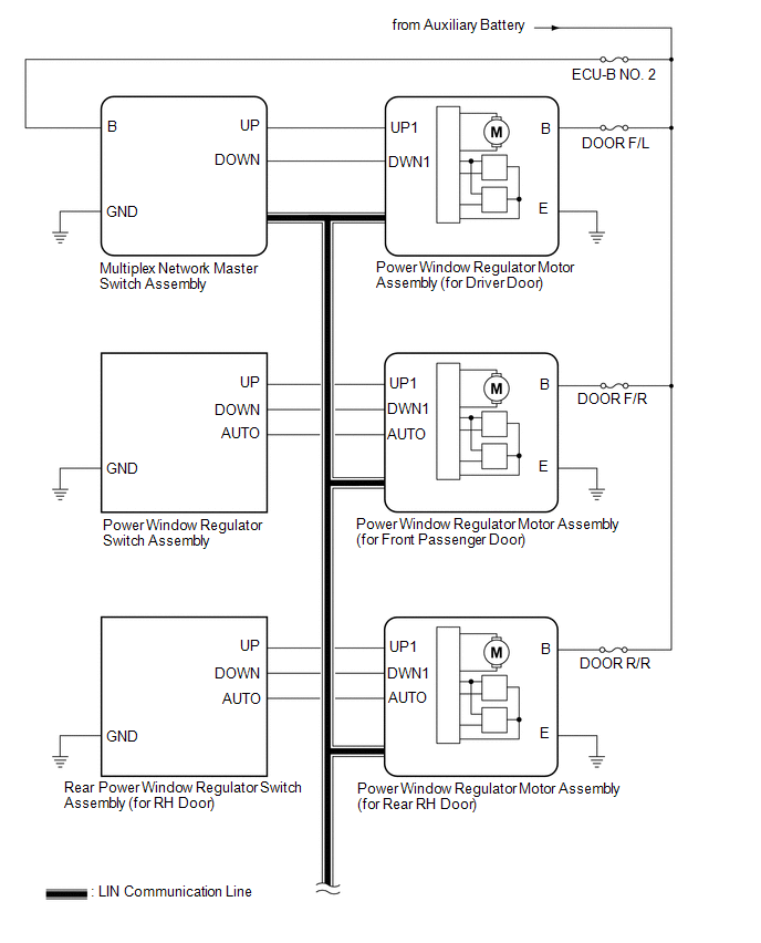
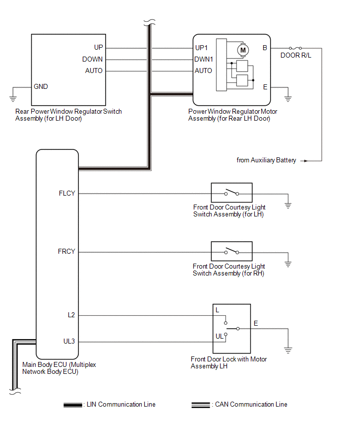
SYSTEM DIAGRAM
.png) Communication Table
Communication Table | Transmitting ECU | Receiving ECU | Signal | Communication Method |
|---|---|---|---|
| Multiplex Network Master Switch Assembly | Power Window Regulator Motor Assembly (for Driver Door) | Power window auto up and down signal | LIN |
| Power window remote up and down signal | LIN | |
| Main Body ECU (Multiplex Network Body ECU) |
| Power window operation permission signal | LIN |
| Certification ECU (Smart Key ECU Assembly) | Main Body ECU (Multiplex Network Body ECU) | Wireless power window operation signal | CAN |
| Main Body ECU (Multiplex Network Body ECU) | Combination Meter Assembly | Window open warning request signal | CAN |
READ NEXT:
 How To Proceed With Troubleshooting
CAUTION / NOTICE / HINT HINT:
Use the following procedure to troubleshoot the power window control system.
*: Use the Techstream.
PROCEDURE 1. VEHICLE BROUGHT TO WORKSHOP
NEXT
Operation Check
OPERATION CHECK CHECK WINDOW LOCK FUNCTION HINT: Before performing the window lock switch operation check, make sure that the window lock switch is off (the switch is not pushed in). (a) Turn the win
Customize Parameters
CUSTOMIZE PARAMETERS CUSTOMIZE POWER WINDOW CONTROL SYSTEM HINT: The following items can be customized. NOTICE:
When the customer requests a change in a function, first make sure that the function
SEE MORE:
Components
COMPONENTS ILLUSTRATION *1 COOL AIR INTAKE DUCT SEAL *2 MILLIMETER WAVE RADAR SENSOR ASSEMBLY N*m (kgf*cm, ft.*lbf): Specified torque - -
Parts Location
PARTS LOCATION ILLUSTRATION *1 SIDE TURN SIGNAL LIGHT ASSEMBLY LH *2 SIDE TURN SIGNAL LIGHT ASSEMBLY RH *3 HEADLIGHT ASSEMBLY LH - HEADLIGHT ECU SUB-ASSEMBLY LH - HEADLIGHT UNIT ASSEMBLY LH (for TMC Made) - HEADLIGHT CORD LH (for Bulb Type Turn Signal Light) (for TMC Made) *4 HEA
© 2016-2026 Copyright www.lexguide.net
