Lexus ES: Components
COMPONENTS
ILLUSTRATION
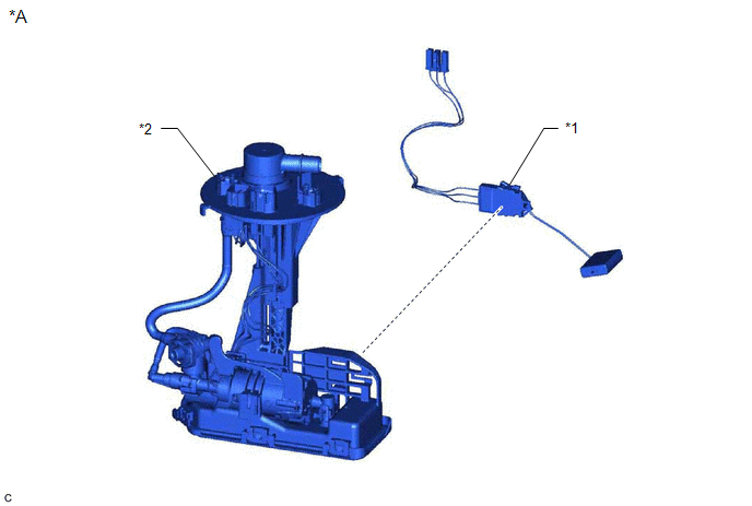
| *A | for Type A | - | - |
| *1 | FUEL SENDER GAUGE ASSEMBLY | *2 | FUEL SUCTION TUBE WITH PUMP AND GAUGE ASSEMBLY |
ILLUSTRATION
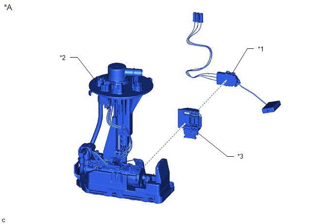
| *A | for Type B | - | - |
| *1 | FUEL SENDER GAUGE ASSEMBLY | *2 | FUEL SUCTION TUBE WITH PUMP AND GAUGE ASSEMBLY |
| *3 | FUEL GAUGE BRACKET | - | - |
READ NEXT:
 Removal
REMOVAL CAUTION / NOTICE / HINT The necessary procedures (adjustment, calibration, initialization or registration) that must be performed after parts are removed and installed, or replaced during fuel
Inspection
INSPECTION PROCEDURE 1. INSPECT FUEL SENDER GAUGE ASSEMBLY CAUTION: Perform the inspection in a well-ventilated area. Do not perform the inspection near an open flame. (a) Check that the float moves s
Installation
INSTALLATION PROCEDURE 1. INSTALL FUEL SENDER GAUGE ASSEMBLY (a) for Type A: (1) Engage the claw to install the fuel sender gauge assembly to the fuel suction tube with pump and gauge assembly. NOTICE
SEE MORE:
Removal
REMOVAL PROCEDURE 1. REMOVE LUGGAGE COMPARTMENT FLOOR MAT Click here 2. REMOVE SPARE WHEEL COVER TRAY Click here 3. REMOVE REAR FLOOR FINISH PLATE Click here 4. REMOVE LUGGAGE COMPARTMENT DOOR WEATHERSTRIP (a) Remove the luggage compartment door weatherstrip.
Installation
INSTALLATION CAUTION / NOTICE / HINT PROCEDURE 1. INSTALL CENTRAL GATEWAY ECU (NETWORK GATEWAY ECU) (a) Engage the 2 claws to install the central gateway ECU (network gateway ECU) as shown in the illustration. Install in this Direction NOTICE: Make sure that the central gateway ECU (networ
© 2016-2026 Copyright www.lexguide.net
