Lexus ES: Removal
REMOVAL
CAUTION / NOTICE / HINT
The necessary procedures (adjustment, calibration, initialization or registration) that must be performed after parts are removed and installed, or replaced during fuel sender gauge assembly removal/installation are shown below.
Necessary Procedures After Parts Removed/Installed/Replaced| Replaced Part or Performed Procedure | Necessary Procedure | Effect/Inoperative Function when Necessary Procedure not Performed | Link |
|---|---|---|---|
|
*: When performing learning using the Techstream.
Click here | |||
| Auxiliary battery terminal is disconnected/reconnected | Perform steering sensor zero point calibration | Lane Control System (for HV Model) | |
| Pre-collision System (for HV Model) | |||
| Parking Support Brake System (for HV Model)* | |||
| Lighting System (for HV Model) | |||
| Memorize steering angle neutral point | Parking Assist Monitor System (for HV Model) | | |
| Panoramic View Monitor System (for HV Model) | | ||
| Initialize power trunk lid system | Power Trunk Lid System (for HV Model) | | |
CAUTION:
-
Never perform work on fuel system components near any possible ignition sources.
.png)
- Vaporized fuel could ignite, resulting in a serious accident.
-
Do not perform work on fuel system components without first disconnecting the cable from the negative (-) auxiliary battery terminal.
.png)
- Sparks could cause vaporized fuel to ignite, resulting in a serious accident.
NOTICE:
- After the power switch is turned off, the radio receiver assembly records various types of memory and settings. As a result, after turning the power switch off, make sure to wait at least 85 seconds before disconnecting the cable from the negative (-) auxiliary battery terminal. (for Audio and Visual System)
- After the power switch is turned off, the radio receiver assembly records various types of memory and settings. As a result, after turning the power switch off, make sure to wait at least 85 seconds before disconnecting the cable from the negative (-) auxiliary battery terminal. (for Navigation System)
PROCEDURE
1. REMOVE FUEL SUCTION TUBE WITH PUMP AND GAUGE ASSEMBLY
Click here .gif)
2. REMOVE FUEL SENDER GAUGE ASSEMBLY
(a) for Type A:
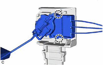
| (1) Disconnect the fuel sender gauge assembly connector. |
|
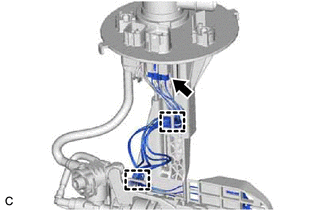
(2) Disengage the 2 clamps to disconnect the wire harness from the fuel suction tube with pump and gauge assembly.
NOTICE:
- Do not damage the wire harness.
- When disengaging each wire harness from the clamp, disengage one wire at a time.
| (3) Disengage the claw to remove the fuel sender gauge assembly from the fuel suction tube with pump and gauge assembly. NOTICE: Be careful not to bend the arm of the fuel sender gauge assembly. |
|
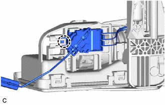
(b) for Type B:
| (1) Disconnect the fuel sender gauge assembly connector. |
|
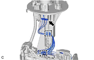
(2) Disengage the 2 clamps to disconnect the wire harness from the fuel suction tube with pump and gauge assembly.
NOTICE:
- Do not damage the wire harness.
- When disengaging each wire harness from the clamp, disengage one wire at a time.
| (3) Disengage the 2 claws to remove the fuel gauge bracket with fuel sender gauge assembly from the fuel suction tube with pump and gauge assembly. NOTICE: Be careful not to bend the arm of the fuel sender gauge assembly. |
|
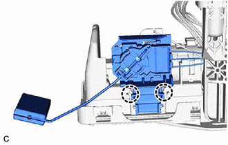
| (4) Disengage the 2 claws to remove the fuel sender gauge assembly from the fuel gauge bracket. |
|
READ NEXT:
 Inspection
INSPECTION PROCEDURE 1. INSPECT FUEL SENDER GAUGE ASSEMBLY CAUTION: Perform the inspection in a well-ventilated area. Do not perform the inspection near an open flame. (a) Check that the float moves s
Installation
INSTALLATION PROCEDURE 1. INSTALL FUEL SENDER GAUGE ASSEMBLY (a) for Type A: (1) Engage the claw to install the fuel sender gauge assembly to the fuel suction tube with pump and gauge assembly. NOTICE
SEE MORE:
Terminals Of Ecu
TERMINALS OF ECU CHECK ABSORBER CONTROL ECU (a) Measure the voltage and resistance according to the value(s) in the table below. NOTICE: Inspect the connectors from the back side while the connectors are connected. Terminal No. (Symbol) Wiring Color Terminal Description Condition Specifi
Test Mode Procedure
TEST MODE PROCEDURE WARNING LIGHT AND INDICATOR LIGHT INITIAL CHECK (a) When the power switch is turned on (IG), check that the ABS warning, brake warning / red (malfunction), brake warning / yellow (minor malfunction), VSC OFF indicator, slip indicator, brake hold standby indicator and brake hold o
