Lexus ES: Components
Lexus ES (XZ10) Service Manual / Engine & Hybrid System / A25a-fxs (fuel) / Fuel Pressure Sensor / Components
COMPONENTS
ILLUSTRATION
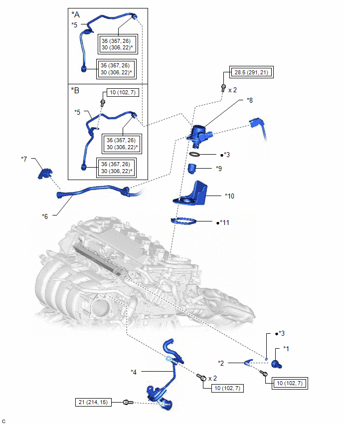
| *A | for EGR Valve Bracket Connection Type | *B | for Cylinder Head Cover Sub-assembly Connection Type |
| *1 | NO. 2 FUEL PRESSURE SENSOR | *2 | NO. 2 FUEL PRESSURE SENSOR HOLDER |
| *3 | O-RING | *4 | NO. 2 WATER BY-PASS PIPE |
| *5 | NO. 1 FUEL PIPE SUB-ASSEMBLY | *6 | FUEL TUBE SUB-ASSEMBLY |
| *7 | FUEL PIPE CLAMP | *8 | FUEL PUMP ASSEMBLY |
| *9 | FUEL PUMP LIFTER ASSEMBLY | *10 | FUEL PUMP FLANGE |
| *11 | FUEL PUMP SPACER GASKET | - | - |
.png) | Tightening torque for "Major areas involving basic vehicle performance such as moving/turning/stopping": N*m (kgf*cm, ft.*lbf) | .png) | N*m (kgf*cm, ft.*lbf): Specified torque |
| * | For use with a union nut wrench | ● | Non-reusable part |
READ NEXT:
 Removal
REMOVAL CAUTION / NOTICE / HINT The necessary procedures (adjustment, calibration, initialization or registration) that must be performed after parts are removed and installed, or replaced during No.
Inspection
INSPECTION PROCEDURE 1. INSPECT NO. 2 FUEL PRESSURE SENSOR (a) Check the No. 2 fuel pressure sensor output voltage. (1) Apply 5 V between terminals 1 (VC) and 3 (E2). NOTICE:
Be careful when c
Installation
INSTALLATION CAUTION / NOTICE / HINT NOTICE: This procedure includes the installation of small-head bolts. Refer to Small-Head Bolts of Basic Repair Hint to identify the small-head bolts. Click here
SEE MORE:
Components
COMPONENTS ILLUSTRATION *1 ENGINE WIRE *2 NO. 1 VACUUM HOSE CONNECTOR *3 VACUUM PUMP ASSEMBLY *4 NO. 1 VACUUM PUMP O-RING Tightening torque for "Major areas involving basic vehicle performance such as moving/turning/stopping": N*m (kgf*cm, ft.*lbf) ● Non-reusable par
Disassembly
DISASSEMBLY PROCEDURE 1. REMOVE GENERATOR PULLEY CAP (a) Remove the generator pulley cap from the generator pulley with clutch. NOTICE:
Do not reuse the generator pulley cap.
If the generator pulley cap is removed, replace the generator pulley cap and generator pulley with clutch with new
© 2016-2026 Copyright www.lexguide.net
