Lexus ES: Removal
REMOVAL
CAUTION / NOTICE / HINT
The necessary procedures (adjustment, calibration, initialization or registration) that must be performed after parts are removed and installed, or replaced during No. 2 fuel pressure sensor removal/installation are shown below.
Necessary Procedures After Parts Removed/Installed/Replaced| Replaced Part or Performed Procedure | Necessary Procedure | Effect/Inoperative Function when Necessary Procedure not Performed | Link |
|---|---|---|---|
|
*: When performing learning using the Techstream.
Click here | |||
| Auxiliary battery terminal is disconnected/reconnected | Perform steering sensor zero point calibration | Lane Control System (for HV Model) | |
| Pre-collision System (for HV Model) | |||
| Parking Support Brake System (for HV Model)* | |||
| Lighting System (for HV Model) | |||
| Memorize steering angle neutral point | Parking Assist Monitor System (for HV Model) | | |
| Panoramic View Monitor System (for HV Model) | | ||
| Initialize power trunk lid system | Power Trunk Lid System (for HV Model) | | |
| Inspection after repair |
| |
CAUTION:
-
Never perform work on fuel system components near any possible ignition sources.
.png)
- Vaporized fuel could ignite, resulting in a serious accident.
-
Do not perform work on fuel system components without first disconnecting the cable from the negative (-) auxiliary battery terminal.
.png)
- Sparks could cause vaporized fuel to ignite, resulting in a serious accident.
-
To prevent serious injury due to fuel spray from the high-pressure fuel lines, always discharge fuel system pressure before removing any fuel system components.
.png)
NOTICE:
- After the power switch is turned off, the radio receiver assembly records various types of memory and settings. As a result, after turning the power switch off, make sure to wait at least 85 seconds before disconnecting the cable from the negative (-) auxiliary battery terminal. (for Audio and Visual System)
- After the power switch is turned off, the radio receiver assembly records various types of memory and settings. As a result, after turning the power switch off, make sure to wait at least 85 seconds before disconnecting the cable from the negative (-) auxiliary battery terminal. (for Navigation System)
-
This procedure includes the removal of small-head bolts. Refer to Small-Head Bolts of Basic Repair Hint to identify the small-head bolts.
Click here
.gif)
PROCEDURE
1. PRECAUTION
NOTICE:
After turning the power switch off, waiting time may be required before disconnecting the cable from the negative (-) auxiliary battery terminal. Therefore, make sure to read the disconnecting the cable from the negative (-) auxiliary battery terminal notices before proceeding with work.
2. DISCHARGE FUEL SYSTEM PRESSURE
Click here
3. DISCONNECT CABLE FROM NEGATIVE AUXILIARY BATTERY TERMINAL
Click here
4. REMOVE THROTTLE BODY WITH MOTOR ASSEMBLY
Click here
5. REMOVE EGR VALVE ASSEMBLY
Click here
6. REMOVE NO. 2 WATER BY-PASS PIPE
Click here
7. DISCONNECT FUEL TUBE SUB-ASSEMBLY
Click here
8. REMOVE NO. 1 FUEL PIPE SUB-ASSEMBLY
Click here
9. REMOVE FUEL PUMP ASSEMBLY
Click here
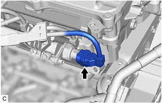
10. REMOVE NO. 2 FUEL PRESSURE SENSOR
| (a) Disconnect the No. 2 fuel pressure sensor connector. |
|
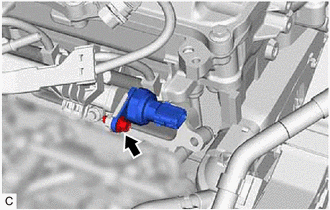
| (b) Using an 8 mm socket wrench, remove the bolt, No. 2 fuel pressure sensor and No. 2 fuel pressure sensor holder from the fuel delivery pipe sub-assembly. |
|
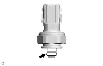
| (c) Remove the O-ring from the No. 2 fuel pressure sensor. |
|
READ NEXT:
 Inspection
INSPECTION PROCEDURE 1. INSPECT NO. 2 FUEL PRESSURE SENSOR (a) Check the No. 2 fuel pressure sensor output voltage. (1) Apply 5 V between terminals 1 (VC) and 3 (E2). NOTICE:
Be careful when c
Installation
INSTALLATION CAUTION / NOTICE / HINT NOTICE: This procedure includes the installation of small-head bolts. Refer to Small-Head Bolts of Basic Repair Hint to identify the small-head bolts. Click here
SEE MORE:
Satellite Radio Broadcast cannot be Selected or After Selecting Broadcast, Broadcast cannot be Added into Memory
CAUTION / NOTICE / HINT NOTICE: Some satellite radio broadcasts require payment. A contract must be made between a satellite radio company and the user. If the contract expires, it will not be possible to listen to the broadcast. PROCEDURE 1. CHECK SATELLITE RADIO (a) Check radio condition.
Radiator Coolant Temperature Sensor Signal Compare Failure (P00B162)
DESCRIPTION This engine uses a No. 2 engine coolant temperature sensor and an intake air temperature sensor to detect temperatures related to engine operation. A thermistor, whose resistance value varies according to the temperature, is built into each sensor. When the temperature becomes low, the r
