Lexus ES: Components
Lexus ES (XZ10) Service Manual / Brake / Brake System (other) / Vacuum Pump (for A25a-fks) / Components
COMPONENTS
ILLUSTRATION
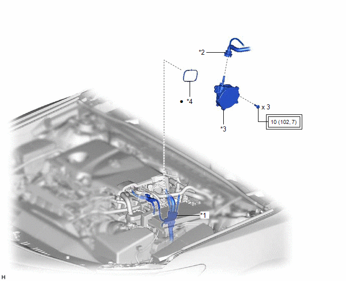
| *1 | ENGINE WIRE | *2 | NO. 1 VACUUM HOSE CONNECTOR |
| *3 | VACUUM PUMP ASSEMBLY | *4 | NO. 1 VACUUM PUMP O-RING |
.png) | Tightening torque for "Major areas involving basic vehicle performance such as moving/turning/stopping": N*m (kgf*cm, ft.*lbf) | ● | Non-reusable part |
ILLUSTRATION

| *1 | END COVER | *2 | VACUUM PUMP HOUSING |
| *3 | VACUUM PUMP ROTOR | *4 | VACUUM PUMP VANE |
| *5 | VACUUM PUMP VANE CAP | *6 | VACUUM PUMP COVER O-RING |
.png) | N*m (kgf*cm, ft.*lbf): Specified torque | ● | Non-reusable part |
.png) | Engine oil | - | - |
READ NEXT:
 Disassembly
DISASSEMBLY PROCEDURE 1. REMOVE END COVER (a) To prevent the coupling of the vacuum pump assembly from contacting the workbench, support the vacuum pump assembly with wooden blocks or an equivalent
Installation
INSTALLATION CAUTION / NOTICE / HINT NOTICE: This procedure includes the installation of small-head bolts. Refer to Small-Head Bolts of Basic Repair Hint to identify the small-head bolts. Click here
On-vehicle Inspection
ON-VEHICLE INSPECTION PROCEDURE 1. OPERATION CHECK (a) Disconnect the No. 1 vacuum hose connector from the vacuum pump assembly. Click here (b) Connect the hose of the vacuum gauge to the vacuum
SEE MORE:
Removal
REMOVAL CAUTION / NOTICE / HINT The necessary procedures (adjustment, calibration, initialization, or registration) that must be performed after parts are removed and installed, or replaced during front brake removal/installation are shown below. Necessary Procedures After Parts Removed/Installed/Re
Lost Communication between Hybrid Powertrain Control Module and Active Grille Air Shutter Missing Message (U129387)
DESCRIPTION This DTC is stored if a communication malfunction occurs between the hybrid vehicle control ECU and swing grille actuator assembly. DTC No. Detection Item DTC Detection Condition Trouble Area U129387 Lost Communication between Hybrid Powertrain Control Module and Active Gr
© 2016-2026 Copyright www.lexguide.net
