Lexus ES: Inspection
INSPECTION
PROCEDURE
1. INSPECT NO. 2 FUEL PRESSURE SENSOR
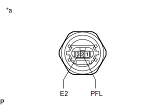
(a) Check the No. 2 fuel pressure sensor output voltage.
| (1) Apply 5 V between terminals 1 (VC) and 3 (E2). NOTICE:
HINT: If a stable power supply is not available, connect 4 nickel-metal hydride batteries (1.2 V each) or equivalent in series. |
|
.png)
| (2) Measure the voltage according to the value(s) in the table below. Standard Voltage:
*: The output voltage changes depending on the voltage applied to the terminals. If the result is not as specified, replace the No. 2 fuel pressure sensor. |
|
READ NEXT:
 Installation
INSTALLATION CAUTION / NOTICE / HINT NOTICE: This procedure includes the installation of small-head bolts. Refer to Small-Head Bolts of Basic Repair Hint to identify the small-head bolts. Click here
Components
COMPONENTS ILLUSTRATION *1 FUEL PRESSURE SENSOR *2 NO. 1 FUEL PRESSURE SENSOR HOLDER Tightening torque for "Major areas involving basic vehicle performance such as moving/turning/stop
SEE MORE:
Disassembly
DISASSEMBLY CAUTION / NOTICE / HINT The necessary procedures (adjustment, calibration, initialization, or registration) that must be performed after parts are removed and installed, or replaced during front door removal/installation are shown below. Necessary Procedure After Parts Removed/Installed/
Components
COMPONENTS ILLUSTRATION *1 DEFROSTER NOZZLE ASSEMBLY *2 NO. 2 SIDE DEFROSTER NOZZLE DUCT *3 NO. 3 HEATER TO REGISTER DUCT *4 TELEPHONE AND GPS ANTENNA ASSEMBLY *5 TELEPHONE AND GPS ANTENNA ASSEMBLY WITH BRACKET *6 TELEPHONE AND GPS ANTENNA BRACKET
