Lexus ES: Components
COMPONENTS
ILLUSTRATION
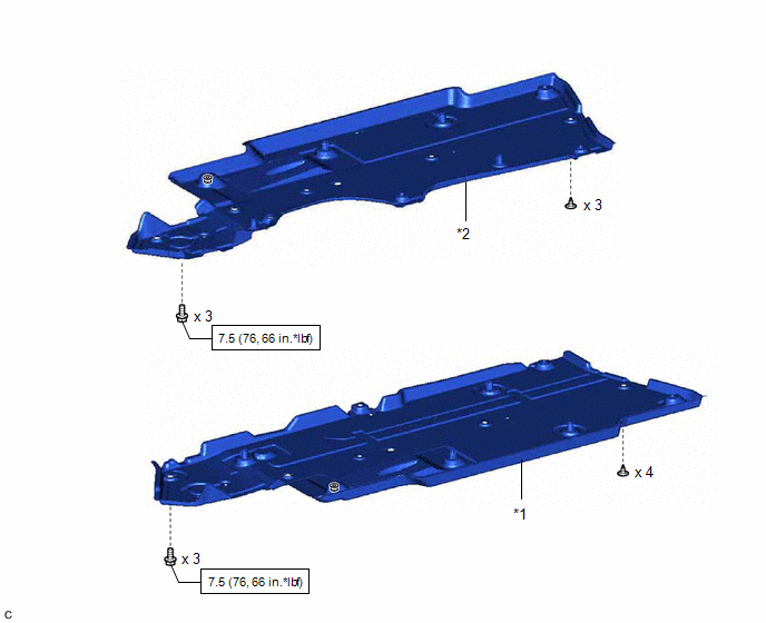
| *1 | FRONT FLOOR COVER LH | *2 | FRONT FLOOR COVER RH |
.png) | N*m (kgf*cm, ft.*lbf): Specified torque | - | - |
ILLUSTRATION
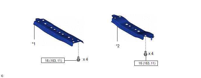
| *1 | CENTER FLOOR CROSSMEMBER BRACE | *2 | FRONT CENTER FLOOR BRACE |
| | N*m (kgf*cm, ft.*lbf): Specified torque | - | - |
ILLUSTRATION
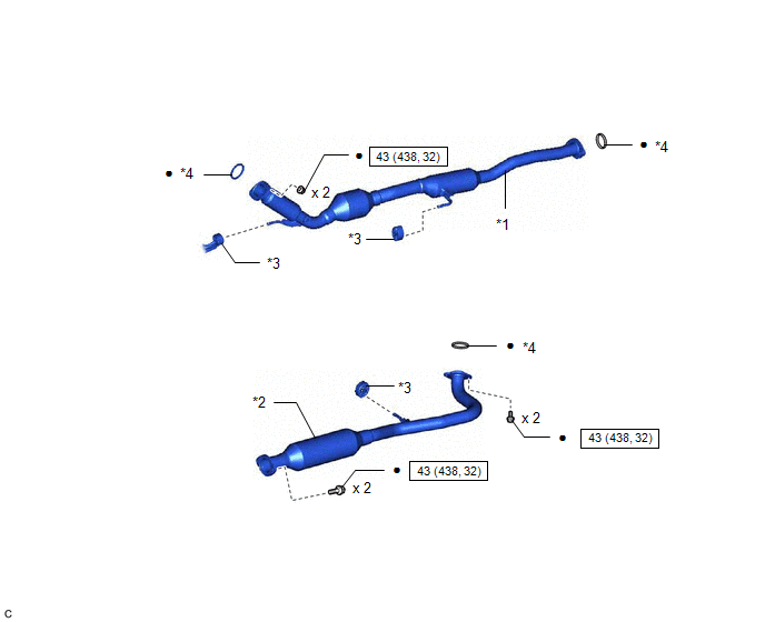
| *1 | FRONT EXHAUST PIPE ASSEMBLY (TWC: Rear Catalyst) | *2 | CENTER EXHAUST PIPE ASSEMBLY |
| *3 | EXHAUST PIPE SUPPORT | *4 | GASKET |
| | N*m (kgf*cm, ft.*lbf): Specified torque | ● | Non-reusable part |
ILLUSTRATION
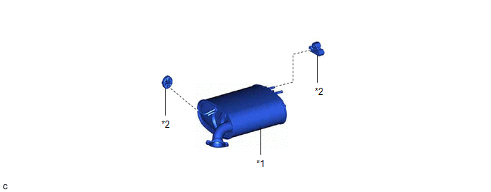
| *1 | TAIL EXHAUST PIPE ASSEMBLY | *2 | EXHAUST PIPE SUPPORT |
READ NEXT:
 Removal
REMOVAL CAUTION / NOTICE / HINT The necessary procedures (adjustment, calibration, initialization or registration) that must be performed after parts are removed and installed, or replaced during fron
Installation
INSTALLATION PROCEDURE 1. INSTALL FRONT EXHAUST PIPE ASSEMBLY (TWC: Rear Catalyst) (a) Install a new gasket to the front exhaust pipe assembly (TWC: Rear Catalyst). (b) Connect the front exhaust pipe
Intake System
On-vehicle InspectionON-VEHICLE INSPECTION CAUTION / NOTICE / HINT The necessary procedures (adjustment, calibration, initialization or registration) that must be performed after parts are removed an
SEE MORE:
Diagnosis System
DIAGNOSIS SYSTEM DESCRIPTION (a) Panoramic moon roof system data and Diagnostic Trouble Codes (DTCs) can be read through the vehicle Data Link Connector 3 (DLC3). When the system seems to be malfunctioning, use the Techstream to check for malfunctions and perform repairs. CHECK DLC3 (a) Check the DL
Cooling System
DESCRIPTION The cause of the malfunction may be the cooling system. Check whether the grille is blocked, whether coolant is leaking, the radiator fan operating condition and whether coolant has frozen. Related Parts Check Area Inspection Grille blockage, coolant amount, coolant hoses, radia
© 2016-2026 Copyright www.lexguide.net
