Lexus ES: Installation
INSTALLATION
PROCEDURE
1. INSTALL FRONT EXHAUST PIPE ASSEMBLY (TWC: Rear Catalyst)
(a) Install a new gasket to the front exhaust pipe assembly (TWC: Rear Catalyst).
(b) Connect the front exhaust pipe assembly (TWC: Rear Catalyst) to the 2 exhaust pipe supports.
(c) Install the front exhaust pipe assembly (TWC: Rear Catalyst) to the exhaust manifold (TWC: Front Catalyst) with 2 new nuts.
Torque:
43 N·m {438 kgf·cm, 32 ft·lbf}
2. INSTALL AIR FUEL RATIO SENSOR (for Sensor 2)
Click here .gif)
3. INSTALL CENTER EXHAUST PIPE ASSEMBLY
(a) Install a new gasket to the front exhaust pipe assembly (TWC: Rear Catalyst).
(b) Connect the center exhaust pipe assembly to the exhaust pipe support.
(c) Install the center exhaust pipe assembly to the front exhaust pipe assembly (TWC: Rear Catalyst) with 2 new bolts.
Torque:
43 N·m {438 kgf·cm, 32 ft·lbf}
4. INSTALL TAIL EXHAUST PIPE ASSEMBLY
(a) Install a new gasket to the center exhaust pipe assembly.
(b) Connect the tail exhaust pipe assembly to the 2 exhaust pipe supports.
(c) Install the tail exhaust pipe assembly to the center exhaust pipe assembly with 2 new bolts.
Torque:
43 N·m {438 kgf·cm, 32 ft·lbf}
5. INSTALL CENTER FLOOR CROSSMEMBER BRACE
(a) Install the center floor crossmember brace to the vehicle body with the 4 bolts.
Torque:
15 N·m {153 kgf·cm, 11 ft·lbf}
6. INSTALL FRONT CENTER FLOOR BRACE
(a) Install the front center floor brace to the vehicle body with the 4 bolts.
Torque:
15 N·m {153 kgf·cm, 11 ft·lbf}
7. INSTALL FRONT FLOOR COVER LH
| (a) Install the front floor cover LH with the grommet (B) and 6 clips (C). |
|
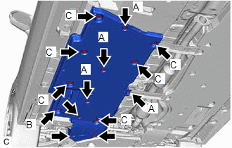
(b) Install the 3 bolts and 4 clips (A).
Torque:
Bolt :
7.5 N·m {76 kgf·cm, 66 in·lbf}
8. INSTALL FRONT FLOOR COVER RH
| (a) Install the front floor cover RH with the grommet (B) and 7 clips (C). |
|
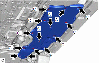
(b) Install the 3 bolts and 3 clips (A).
Torque:
Bolt :
7.5 N·m {76 kgf·cm, 66 in·lbf}
9. INSPECT FOR EXHAUST GAS LEAK
If gas is leaking, tighten the areas necessary to stop the leak. Replace damaged parts as necessary.
(a) Perform "Inspection After Repair" after repairing an exhaust gas leak.
Click here
READ NEXT:
 Intake System
On-vehicle InspectionON-VEHICLE INSPECTION CAUTION / NOTICE / HINT The necessary procedures (adjustment, calibration, initialization or registration) that must be performed after parts are removed an
Lubrication System
On-vehicle InspectionON-VEHICLE INSPECTION PROCEDURE 1. CHECK ENGINE OIL LEVEL (a) Warm up and stop the engine, then wait for 5 minutes. (b) Check that the engine oil level is between the low level a
SEE MORE:
Removal
REMOVAL CAUTION / NOTICE / HINT The necessary procedures (adjustment, calibration, initialization or registration) that must be performed after parts are removed and installed, or replaced during fuel pressure sensor removal/installation are shown below. Necessary Procedures After Parts Removed/Inst
Restraints Occupant Classification System Module Communication Stop Mode
DESCRIPTION Detection Item Symptom Trouble Area Restraints Occupant Classification System Module Communication Stop Mode Any of the following conditions are met:
Communication stop for "Occupant Detection" is indicated on the "Communication Bus Check" screen of the Techstream.
Click
