Lexus ES: Removal
REMOVAL
CAUTION / NOTICE / HINT
The necessary procedures (adjustment, calibration, initialization or registration) that must be performed after parts are removed and installed, or replaced during front exhaust pipe assembly (TWC: Rear Catalyst), center exhaust pipe assembly and tail exhaust pipe assembly removal/installation are shown below.
Necessary Procedures After Parts Removed/Installed/Replaced| Replaced Part or Performed Procedure | Necessary Procedure | Effect/Inoperative Function when Necessary Procedure not Performed | Link |
|---|---|---|---|
| Inspection After Repair |
| |
CAUTION:
To prevent burns, do not touch the engine, exhaust pipe or other high temperature components while the engine is hot.
.png)
PROCEDURE
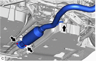
1. REMOVE TAIL EXHAUST PIPE ASSEMBLY
CAUTION:
To prevent burns, do not touch the engine, exhaust pipe or other high temperature components while the engine is hot.
| (a) Remove the 2 bolts and disconnect the tail exhaust pipe assembly from the center exhaust pipe assembly. |
|
(b) Remove the tail exhaust pipe assembly from the 2 exhaust pipe supports.
(c) Remove the gasket from the center exhaust pipe assembly.
2. REMOVE CENTER EXHAUST PIPE ASSEMBLY
CAUTION:
To prevent burns, do not touch the engine, exhaust pipe or other high temperature components while the engine is hot.
| (a) Remove the 2 bolts and disconnect the center exhaust pipe assembly from the front exhaust pipe assembly (TWC: Rear Catalyst). |
|
(b) Remove the center exhaust pipe assembly from the exhaust pipe support.
(c) Remove the gasket from the front exhaust pipe assembly (TWC: Rear Catalyst).
3. REMOVE FRONT FLOOR COVER LH
| (a) Remove the 3 bolts and 4 clips (A). |
|

(b) Disengage the grommet (B) and 6 clips (C) to remove the front floor cover LH.
4. REMOVE FRONT FLOOR COVER RH
| (a) Remove the 3 bolts and 3 clips (A). |
|

(b) Disengage the grommet (B) and 7 clips (C) to remove the front floor cover RH.
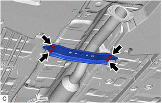
5. REMOVE FRONT CENTER FLOOR BRACE
| (a) Remove the 4 bolts and front center floor brace from the vehicle body. |
|
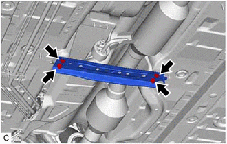
6. REMOVE CENTER FLOOR CROSSMEMBER BRACE
| (a) Remove the 4 bolts and center floor crossmember brace from the vehicle body. |
|
7. REMOVE AIR FUEL RATIO SENSOR (for Sensor 2)
Click here .gif)
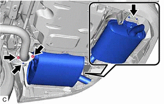
8. REMOVE FRONT EXHAUST PIPE ASSEMBLY (TWC: Rear Catalyst)
CAUTION:
To prevent burns, do not touch the engine, exhaust pipe or other high temperature components while the engine is hot.
| (a) Remove the 2 nuts and disconnect the front exhaust pipe assembly (TWC: Rear Catalyst) from the exhaust manifold (TWC: Front Catalyst). |
|
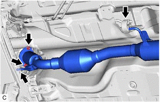
(b) Remove the front exhaust pipe assembly (TWC: Rear Catalyst) from the 2 exhaust pipe supports.
(c) Remove the gasket from the front exhaust pipe assembly (TWC: Rear Catalyst).
READ NEXT:
 Installation
INSTALLATION PROCEDURE 1. INSTALL FRONT EXHAUST PIPE ASSEMBLY (TWC: Rear Catalyst) (a) Install a new gasket to the front exhaust pipe assembly (TWC: Rear Catalyst). (b) Connect the front exhaust pipe
Intake System
On-vehicle InspectionON-VEHICLE INSPECTION CAUTION / NOTICE / HINT The necessary procedures (adjustment, calibration, initialization or registration) that must be performed after parts are removed an
SEE MORE:
Lost Communication with Front Shade Module (B2346)
DESCRIPTION This DTC is stored when LIN communication between the sliding roof ECU (sliding roof drive gear assembly) and roof sunshade ECU (sliding roof drive gear assembly) stops for 10 seconds or more. DTC No. Detection Item DTC Detection Condition Trouble Area B2346 Lost Communica
Drive Motor "A" Inverter Voltage Sensor(VH) Circuit Voltage Above Threshold (P0C7917)
DTC SUMMARY MALFUNCTION DESCRIPTION If an overvoltage malfunction occurs in the motor inverter or generator inverter, the motor generator control ECU (MG ECU) detects the malfunction and stores this DTC. The cause of this malfunction may be one of the following: Area Main Malfunction Descriptio
