Lexus ES: Components
COMPONENTS
ILLUSTRATION
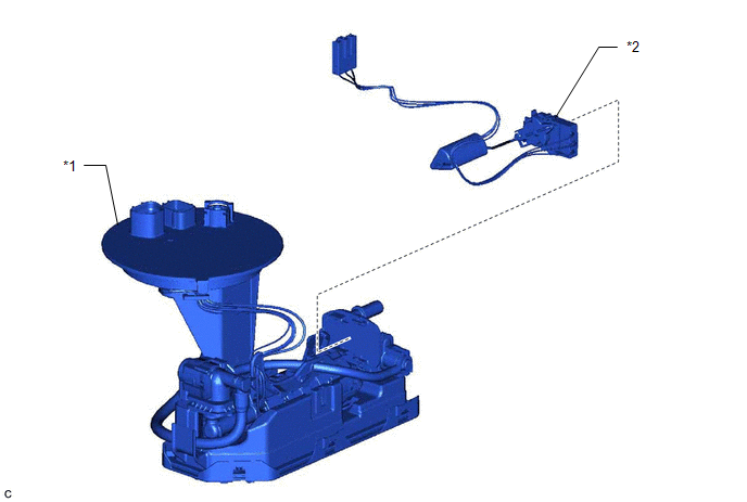
| *1 | FUEL SUCTION TUBE WITH PUMP AND GAUGE ASSEMBLY | *2 | FUEL SENDER GAUGE ASSEMBLY |
ILLUSTRATION
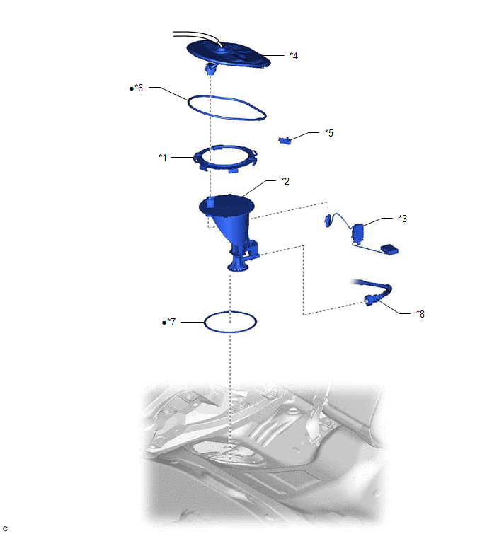
| *1 | FUEL PUMP GAUGE RETAINER | *2 | FUEL TANK VENT TUBE ASSEMBLY |
| *3 | NO. 2 FUEL SENDER GAUGE ASSEMBLY | *4 | REAR FLOOR SERVICE HOLE COVER |
| *5 | NO. 1 FUEL TUBE CLAMP | *6 | BUTYL TAPE |
| *7 | FUEL SUCTION TUBE SET GASKET | *8 | FUEL RETURN VENT TUBE SUB-ASSEMBLY |
| ● | Non-reusable part | - | - |
READ NEXT:
 Inspection
INSPECTION PROCEDURE 1. INSPECT FUEL SENDER GAUGE ASSEMBLY CAUTION: Perform the inspection in a well-ventilated area. Do not perform the inspection near an open flame. (a) Check that the float moves s
Installation
INSTALLATION PROCEDURE 1. INSTALL NO. 2 FUEL SENDER GAUGE ASSEMBLY (a) Engage the claw to install the No. 2 fuel sender gauge assembly to the fuel tank vent tube assembly. NOTICE: Be careful not to be
SEE MORE:
On-vehicle Inspection
ON-VEHICLE INSPECTION PROCEDURE 1. CHECK STEERING EFFORT (TORQUE) NOTICE: These service operations may affect the SRS airbags. Be sure to read the precautionary notices concerning the SRS airbag system before servicing. Click here (a) Stop the vehicle on a level, paved surface and align the wheel
Parts Location
PARTS LOCATION ILLUSTRATION *1 ECM *2 FUEL TANK ASSEMBLY *3 FUEL PUMP CONTROL ECU *4 FUEL SUCTION TUBE WITH PUMP AND GAUGE ASSEMBLY - FUEL PUMP (for Low Pressure) - FUEL SENDER GAUGE ASSEMBLY - FUEL MAIN VALVE ASSEMBLY (for Low Pressure) - FUEL MAIN VALVE ASSEMBLY (for High Press
© 2016-2026 Copyright www.lexguide.net
