Lexus ES: Inspection
INSPECTION
PROCEDURE
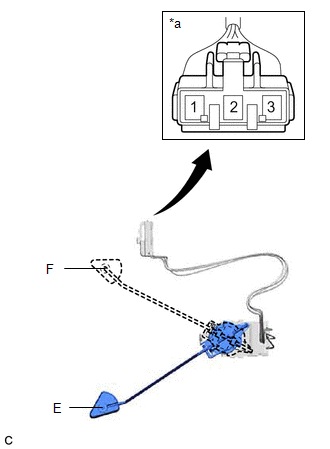
1. INSPECT FUEL SENDER GAUGE ASSEMBLY
CAUTION:
Perform the inspection in a well-ventilated area.
Do not perform the inspection near an open flame.
(a) Check that the float moves smoothly between F and E.
(b) Check the fuel sender gauge assembly voltage.
| (1) Apply 5 V between terminals 2 and 3. NOTICE:
HINT: If a stable power supply is not available, connect 4 nickel-metal hydride batteries (1.2 V each) or equivalent in series. |
|
.png)
| (2) Measure the voltage according to the value(s) in the table below. Standard Voltage:
*: The output voltage changes depending on the voltage applied to the terminals. Output voltage (F) = (0.851 x Voltage applied to terminals) to (0.921 x Voltage applied to terminals) Output voltage (E) = (0.069 x Voltage applied to terminals) to (0.139 x Voltage applied to terminals) If the result is not as specified, replace the fuel sender gauge assembly. |
|
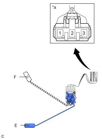
2. INSPECT NO. 2 FUEL SENDER GAUGE ASSEMBLY
CAUTION:
Perform the inspection in a well-ventilated area.
Do not perform the inspection near an open flame.
(a) Check that the float moves smoothly between F and E.
(b) Check the No. 2 fuel sender gauge assembly voltage.
| (1) Apply 5 V between terminals 2 and 3. NOTICE:
HINT: If a stable power supply is not available, connect 4 nickel-metal hydride batteries (1.2 V each) or equivalent in series. |
|
| (2) Measure the voltage according to the value(s) in the table below. Standard Voltage:
*: The output voltage changes depending on the voltage applied to the terminals. Output voltage (F) = (0.851 x Voltage applied to terminals) to (0.921 x Voltage applied to terminals) Output voltage (E) = (0.069 x Voltage applied to terminals) to (0.139 x Voltage applied to terminals) If the result is not as specified, replace the No. 2 fuel sender gauge assembly. |
|
READ NEXT:
 Installation
INSTALLATION PROCEDURE 1. INSTALL NO. 2 FUEL SENDER GAUGE ASSEMBLY (a) Engage the claw to install the No. 2 fuel sender gauge assembly to the fuel tank vent tube assembly. NOTICE: Be careful not to be
Precaution
PRECAUTION CAUTION:
Never perform work on fuel system components near any possible ignition sources.
Vaporized fuel could ignite, resulting in a serious accident.
Do not perform work on fuel s
SEE MORE:
Diagnostic Trouble Code Chart
DIAGNOSTIC TROUBLE CODE CHART Power Tilt and Power Telescopic Steering Column System DTC No. Detection Item DTC Detection Condition Link B26031C Tilt and Telescopic Manual Switch Circuit Circuit Voltage Out of Range When operating the tilt and telescopic switch, an abnormal voltage
FR Speed Sensor Wrong Installation (X0452)
DESCRIPTION Code Tester Display Measurement Item Trouble Area X0452 FR Speed Sensor Wrong Installation History of front speed sensor RH being installed incorrectly Front Speed Sensor RH PROCEDURE 1. CHECK FOR DTCs (HEALTH CHECK) (a) Perform the Health Check using the T
