Lexus ES: Installation
INSTALLATION
PROCEDURE
1. INSTALL NO. 2 FUEL SENDER GAUGE ASSEMBLY
(a) Engage the claw to install the No. 2 fuel sender gauge assembly to the fuel tank vent tube assembly.
NOTICE:
Be careful not to bend the arm of the No. 2 fuel sender gauge assembly.
(b) Engage the 2 clamps to connect the wire harness to the fuel tank vent tube assembly.
NOTICE:
- Do not damage the wire harness.
- When engaging each wire harness to the clamp, engage one wire at a time.
(c) Connect the No. 2 fuel sender gauge assembly connector.
2. INSTALL FUEL TANK VENT TUBE ASSEMBLY
(a) Install a new fuel suction tube set gasket to the fuel tank assembly.
(b) Connect the fuel return vent tube sub-assembly and set the fuel tank vent tube assembly to the fuel tank assembly.
Click here .gif)
NOTICE:
- When connecting the fuel tube connector, do not excessively pull on the fuel return vent tube sub-assembly.
- Be careful not to bend the arm of the No. 2 fuel sender gauge assembly.
(c) Align the protrusions of the fuel tank vent tube assembly with the notches in the fuel tank assembly.
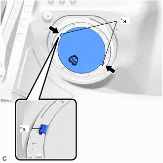
| *a | Protrusion |
.png) | Notch |
3. INSTALL FUEL PUMP GAUGE RETAINER
(a) Install the fuel pump gauge retainer.
(1) While pressing down on the fuel tank vent tube assembly, temporarily install the fuel pump gauge retainer.
| (2) Temporarily install SST (plate) and SST (claw) to the fuel pump gauge retainer. SST: 09808-01071 SST: 09808-14031 09808-01030 09808-01090 HINT: Securely insert the ends of SST (claw) into the insertion points in the fuel pump gauge retainer. |
|
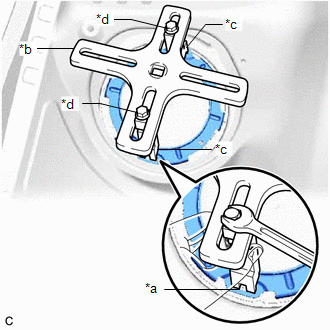
(3) While firmly pressing SST (claw) into the insertion points in the fuel pump gauge retainer, tighten SST (bolt).
(4) Install SST (handle) to SST (plate).
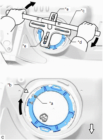
| *a | Triangle Mark (Fuel Pump Gauge Retainer) |
| *b | Triangle Mark (Fuel Tank Assembly) |
| *c | SST (Handle) |
| *d | SST (Plate) |
| *e | SST (Bolt) |
.png) | Front Side |
SST: 09808-14031
09808-01010
(5) Using SST, rotate the fuel pump gauge retainer so that the triangle mark on the fuel pump gauge retainer is aligned with the triangle mark on the fuel tank assembly to install the fuel tank vent tube assembly to the fuel tank assembly.
NOTICE:
- Do not use any tools other than specified as this may result in damage to the fuel pump gauge retainer or fuel tank assembly.
- Do not press down on SST excessively as this may make the fuel pump gauge retainer hard to rotate, and may damage components.
- Make sure to rotate SST (handle) horizontally. If it is rotated at an angle, SST may come off.
- Do not spin SST too fast or use an impact wrench as this may result in damage to components.
- If SST comes off of the fuel pump gauge retainer, loosen SST (bolt) and reinstall SST.
- Make sure that the fuel suction tube set gasket does not come off.
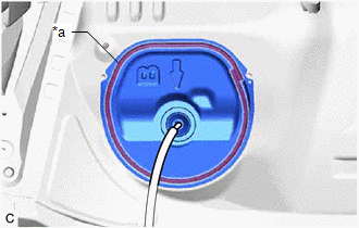
(b) Engage the claw to install the No. 1 fuel tube clamp.
4. INSTALL REAR FLOOR SERVICE HOLE COVER
(a) Remove any remaining butyl tape from the rear floor service hole cover and vehicle body.
(b) Clean the installation surfaces of the rear floor service hole cover and vehicle body.
(c) Connect the fuel tank vent tube assembly connector.
| (d) Install the rear floor service hole cover with new butyl tape. NOTICE: Securely install the rear floor service hole cover. |
|
5. INSTALL FUEL SENDER GAUGE ASSEMBLY
(a) Engage the 2 claws to install the fuel sender gauge assembly to the fuel suction tube with pump and gauge assembly.
NOTICE:
Be careful not to bend the arm of the fuel sender gauge assembly.
(b) Engage the 3 clamps to connect the wire harness to the fuel suction tube with pump and gauge assembly.
NOTICE:
- Do not damage the wire harness.
- When engaging each wire harness to the clamp, engage one wire at a time.
(c) Connect the fuel sender gauge assembly connector.
6. INSTALL FUEL SUCTION TUBE WITH PUMP AND GAUGE ASSEMBLY
Click here
READ NEXT:
 Precaution
PRECAUTION CAUTION:
Never perform work on fuel system components near any possible ignition sources.
Vaporized fuel could ignite, resulting in a serious accident.
Do not perform work on fuel s
Parts Location
PARTS LOCATION ILLUSTRATION *1 ECM *2 FUEL TANK ASSEMBLY *3 FUEL PUMP CONTROL ECU *4 FUEL SUCTION TUBE WITH PUMP AND GAUGE ASSEMBLY - FUEL PUMP (for Low Pressure) - FUEL MAIN VALVE
SEE MORE:
Error in Matching of ECUs (C1567)
DESCRIPTION The power steering ECU (rack and pinion power steering gear assembly) determines whether an incompatible hybrid vehicle control ECU or skid control ECU (brake booster with master cylinder assembly) is installed based on the identification information. DTC No. Detection Item DTC De
Data List / Active Test
DATA LIST / ACTIVE TEST NOTICE:
In the table below, the values listed under "Normal Condition" are reference values. Do not depend solely on these reference values when deciding whether a part is faulty or not.
When diagnosing symptoms such as hesitation, rough idle, or other small symptoms usi
