Lexus ES: Parts Location
Lexus ES (XZ10) Service Manual / Engine & Hybrid System / 2gr-fks (fuel) / Fuel System / Parts Location
PARTS LOCATION
ILLUSTRATION
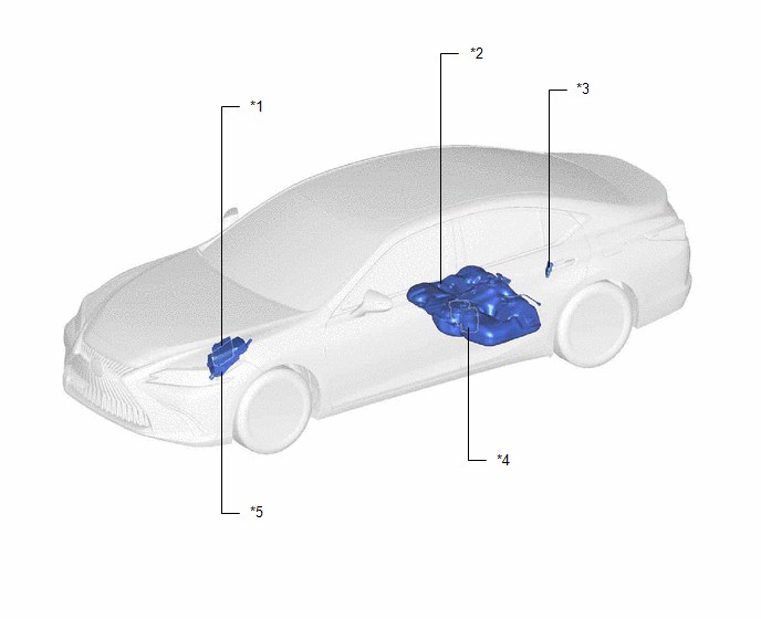
| *1 | ECM | *2 | FUEL TANK ASSEMBLY |
| *3 | FUEL PUMP CONTROL ECU | *4 | FUEL SUCTION TUBE WITH PUMP AND GAUGE ASSEMBLY - FUEL PUMP (for Low Pressure) - FUEL SENDER GAUGE ASSEMBLY - FUEL MAIN VALVE ASSEMBLY (for Low Pressure) - FUEL MAIN VALVE ASSEMBLY (for High Pressure) |
| *5 | NO. 1 ENGINE ROOM RELAY BLOCK ASSEMBLY AND NO. 1 ENGINE ROOM JUNCTION BLOCK ASSEMBLY - EFI-MAIN NO. 2 RELAY - IG2 NO. 1 RELAY - INJ FUSE | - | - |
ILLUSTRATION
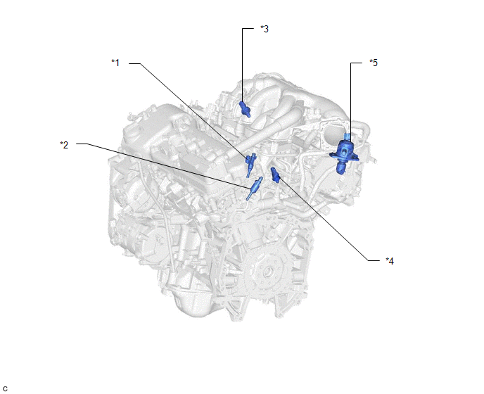
| *1 | PORT FUEL INJECTOR ASSEMBLY | *2 | DIRECT FUEL INJECTOR ASSEMBLY |
| *3 | FUEL PRESSURE SENSOR (FUEL DELIVERY PIPE WITH SENSOR ASSEMBLY) (for Low Pressure) | *4 | FUEL PRESSURE SENSOR (FUEL DELIVERY PIPE WITH SENSOR ASSEMBLY LH) (for High Pressure) |
| *5 | FUEL PUMP ASSEMBLY (for High Pressure) | - | - |
READ NEXT:
 System Diagram
SYSTEM DIAGRAM HIGH PRESSURE SIDE FUEL SYSTEM WIRING DIAGRAM LOW PRESSURE SIDE FUEL SYSTEM WIRING DIAGRAM
On-vehicle Inspection
ON-VEHICLE INSPECTION PROCEDURE 1. CHECK FUEL PUMP WITH FILTER ASSEMBLY OPERATION AND INSPECT FOR FUEL LEAK (a) Check fuel pump operation. (1) Connect the Techstream to the DLC3. (2) Turn the engine s
SEE MORE:
Windshield Deicer does not Operate
DESCRIPTION When the front wiper deicer switch is operated, the operation signal is transmitted to the air conditioning amplifier assembly directly. When the air conditioning amplifier assembly receives the signal, it turns on the DEICER relay to operate the windshield deicer system. WIRING DIAGRAM
Slave Module Horizontal Axis Misalignment (C1AC2)
DESCRIPTION This DTC is stored when the angle of the blind spot monitor sensor LH deviates more than the allowable range from the horizontal axis. HINT:
If a drum tester such as a speedometer tester, brake/speedometer combination tester or chassis dynamometer is used with the blind spot monitor s
© 2016-2026 Copyright www.lexguide.net
