Lexus ES: Components
COMPONENTS
ILLUSTRATION
.png)
| *1 | REAR SEAT INNER BELT ASSEMBLY LH | *2 | REAR CENTER SEAT LAP TYPE BELT ASSEMBLY |
| *3 | WASHER | *4 | REAR SEAT CUSHION ASSEMBLY |
| *5 | REAR SEAT CUSHION LOCK HOOK | - | - |
.png) | Tightening torque for "Major areas involving basic vehicle performance such as moving/turning/stopping": N*m (kgf*cm, ft.*lbf) | ● | Non-reusable part |
ILLUSTRATION
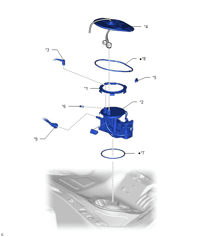
| *1 | FUEL PUMP GAUGE RETAINER | *2 | FUEL SUCTION TUBE WITH PUMP AND GAUGE ASSEMBLY |
| *3 | FUEL TANK MAIN TUBE SUB-ASSEMBLY | *4 | REAR FLOOR SERVICE HOLE COVER |
| *5 | NO. 1 FUEL TUBE CLAMP | *6 | TUBE JOINT CLIP |
| *7 | FUEL SUCTION TUBE SET GASKET | *8 | BUTYL TAPE |
| *9 | FUEL RETURN VENT TUBE SUB-ASSEMBLY | - | - |
| ● | Non-reusable part | - | - |
ILLUSTRATION
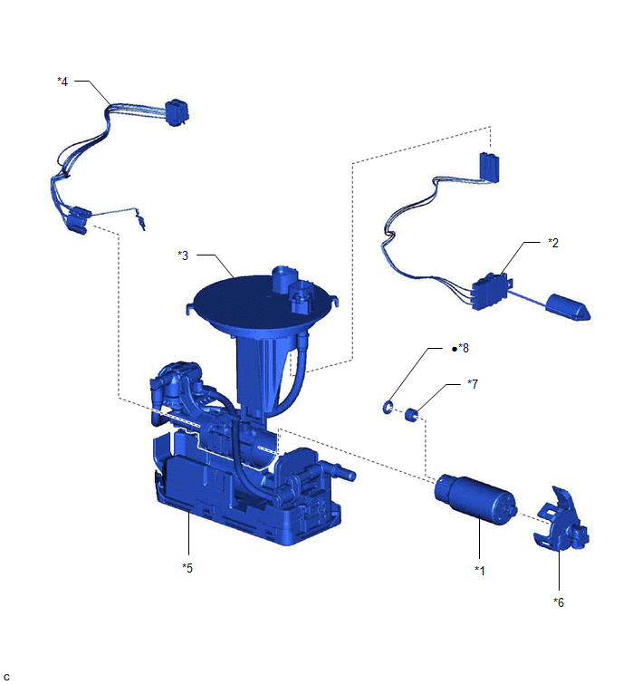
| *1 | FUEL PUMP | *2 | FUEL SENDER GAUGE ASSEMBLY |
| *3 | FUEL SUCTION PLATE SUB-ASSEMBLY | *4 | FUEL PUMP HARNESS |
| *5 | FUEL SUB-TANK SUB-ASSEMBLY | *6 | NO. 2 FUEL SUCTION SUPPORT |
| *7 | FUEL PUMP SPACER | *8 | O-RING |
| ● | Non-reusable part | - | - |
READ NEXT:
 Disassembly
DISASSEMBLY CAUTION / NOTICE / HINT NOTICE: Do not disconnect the tube shown in the illustration when disassembling the fuel suction tube with pump and gauge assembly. Doing so will cause reassembly o
Inspection
INSPECTION PROCEDURE 1. INSPECT FUEL PUMP (a) Measure the resistance according to the value(s) in the table below. Standard Resistance: Tester Connection Specified Condition U - V 0.05
Reassembly
REASSEMBLY PROCEDURE 1. INSTALL FUEL PUMP HINT: Perform "Inspection After Repair" after replacing the fuel pump. Click here (a) Apply gasoline to a new O-ring. Then install the O-ring and fuel pu
SEE MORE:
Data List / Active Test
DATA LIST / ACTIVE TEST DATA LIST NOTICE: In the table below, the values listed under "Normal Condition" are reference values. Do not depend solely on these reference values when deciding whether a part is faulty or not. HINT: Using the Techstream to read the Data List allows the values or states of
Cylinder 1 Injector "A" Circuit Open (P020113-P020413,P062D13)
DESCRIPTION The D-4S system has two fuel injection systems. One is an in-cylinder direct injection system that directly injects pressurized fuel into the combustion chamber. The other is an intake port injection system. The ECM determines which fuel injection system to use in accordance with the eng
