Lexus ES: Reassembly
REASSEMBLY
PROCEDURE
1. INSTALL FUEL PUMP
HINT:
Perform "Inspection After Repair" after replacing the fuel pump.
Click here .gif)
| (a) Apply gasoline to a new O-ring. Then install the O-ring and fuel pump spacer to the fuel pump. |
|
.png)
(b) Install the fuel pump to the fuel suction plate sub-assembly.
NOTICE:
Make sure that the O-ring is not cut or pinched during installation.
(c) Engage the 3 claws to install the No. 2 fuel suction support to the fuel suction plate sub-assembly.
(d) Engage the 4 claws to install the fuel suction plate sub-assembly to the fuel sub-tank sub-assembly.
(e) Align the protrusion of the fuel sub-tank sub-assembly with the installation hole of the fuel suction plate sub-assembly and then slide the fuel suction plate sub-assembly to install the fuel sub-tank sub-assembly.
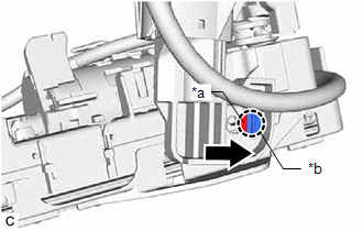
| *a | Protrusion |
| *b | Installation Hole |
.png) | Slide |
(f) Engage the clamp to install the fuel pump harness to the fuel suction tube with pump and gauge assembly.
NOTICE:
- Do not damage the wire harness.
- When engaging each wire harness to the clamp, engage one wire at a time.
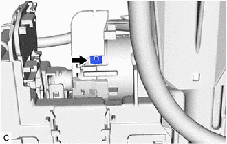
(g) Engage the claw and connect the ground terminal of the fuel pump harness.
NOTICE:
- Securely engage the claw.
- Make sure that there is no foreign matter between the fuel pump and the ground terminal of the fuel pump harness.
- Make sure that the ground terminal of the fuel pump harness is securely connected to the fuel pump body.
| (h) Check the connection state of the fuel pump harness. (1) Measure the resistance according to the value(s) in the table below. Standard Resistance:
If the result is not as specified, reconnect the fuel pump harness to the fuel pump so that the ground terminal of the fuel pump harness is securely connected to the fuel pump body. |
|
(i) Connect the 3 fuel pump harness connectors.
2. INSTALL FUEL SENDER GAUGE ASSEMBLY
Click here
READ NEXT:
 Installation
INSTALLATION PROCEDURE 1. INSTALL FUEL SUCTION TUBE WITH PUMP AND GAUGE ASSEMBLY (a) Install a new fuel suction tube set gasket to the fuel tank assembly. (b) Connect the fuel return vent tube sub-ass
Fuel Pump (for High Pressure)
ComponentsCOMPONENTS ILLUSTRATION *1 NO. 1 FUEL PIPE SUB-ASSEMBLY *2 FUEL PUMP ASSEMBLY *3 FUEL TUBE SUB-ASSEMBLY *4 FUEL PUMP LIFTER ASSEMBLY *5 FUEL PUMP FLANGE *6 FUE
Fuel Pump Ecu
ComponentsCOMPONENTS ILLUSTRATION *A w/ Silencer Sheet - - *1 FUEL PUMP CONTROL ECU *2 FUEL PUMP CONTROL ECU BRACKET *3 REAR SEAT SIDE GARNISH LH *4 REAR DOOR SCUFF PLAT
SEE MORE:
Disassembly
DISASSEMBLY PROCEDURE 1. REMOVE SLIDING ROOF DRIVE GEAR SUB-ASSEMBLY (a) Remove the bolt. Remove in this Direction (b) Disengage the claw and guide as shown in the illustration to remove the map light bracket. (c) Remove the 2 bolts and sliding roof drive gear sub-assembly.
Disassembly
DISASSEMBLY CAUTION / NOTICE / HINT The necessary procedures (adjustment, calibration, initialization, or registration) that must be performed after parts are removed and installed, or replaced during cylinder block removal/installation are shown below. Necessary Procedure After Parts Removed/Instal
