Lexus ES: Cylinder 1 Injector "A" Circuit Open (P020113-P020413,P062D13)
DESCRIPTION
The D-4S system has two fuel injection systems. One is an in-cylinder direct injection system that directly injects pressurized fuel into the combustion chamber. The other is an intake port injection system. The ECM determines which fuel injection system to use in accordance with the engine conditions. The direct injection system uses an injector driver (EDU) built into the ECM to rapidly operate the direct fuel injector assemblies. It converts injection request signals from the ECM to high-voltage and high-current injector-drive signals that drive the direct fuel injector assemblies.
| DTC No. | Detection Item | DTC Detection Condition | Trouble Area | MIL | Memory | Note |
|---|---|---|---|---|---|---|
| P020113 | Cylinder 1 Injector "A" Circuit Open | One of following conditions is met (1 trip detection logic):
|
| Comes on | DTC stored | SAE Code: P0201 |
| P020213 | Cylinder 2 Injector "A" Circuit Open | One of following conditions is met (1 trip detection logic):
|
| Comes on | DTC stored | SAE Code: P0202 |
| P020313 | Cylinder 3 Injector "A" Circuit Open | One of following conditions is met (1 trip detection logic):
|
| Comes on | DTC stored | SAE Code: P0203 |
| P020413 | Cylinder 4 Injector "A" Circuit Open | One of following conditions is met (1 trip detection logic):
|
| Comes on | DTC stored | SAE Code: P0204 |
| P062D13 | Fuel Injector Driver Circuit Performance Bank 1 Circuit Open | Open or short in direct fuel injector assembly (all cylinders) circuits for 60 times or more (1 trip detection logic). |
| Comes on | DTC stored | SAE Code: P062D |
MONITOR DESCRIPTION
The fuel injection sequence occurs in numerical order from No. 1 to No. 4.
The ECM monitors the Injector Driver (EDU) at all times. If drivers or direct fuel injector assembly is malfunctioning, the EDU sends direct fuel injector assembly operation condition signals (fail signals) to the ECM. When the ECM receives the signals, the ECM stops the fuel injection control of the appropriate cylinders, cuts voltage to the appropriate D INJ relay, and illuminates the MIL.
MONITOR STRATEGY
| Related DTCs | P0201: Injector circuit open (cylinder 1) P0202: Injector circuit open (cylinder 2) P0203: Injector circuit open (cylinder 3) P0204: Injector circuit open (cylinder 4) P062D: Injector driver performance |
| Required Sensors/Components (Main) | Direct fuel injector assembly ECM (injector driver) |
| Required Sensors/Components (Related) | - |
| Frequency of Operation | Continuous |
| Duration | - |
| MIL Operation | Immediate |
| Sequence of Operation | None |
TYPICAL ENABLING CONDITIONS
P0201, P0202, P0203 and P0204| All of the following conditions are met | - |
| Confirmed injection | 2 times or more |
| Either of the following conditions is met | A or B |
| A. All of the following conditions are met | (a), (b) and (c) |
| (a) Starter | Off |
| (b) Auxiliary battery voltage | 10.5 V or higher |
| (c) Time after condition (b) is met | 0.5 seconds or more |
| B. All of the following conditions are met | (d), (e) and (f) |
| (d) Starter | On |
| (e) Auxiliary battery voltage | 8 V or higher |
| (f) Time after condition (e) is met | 0.5 seconds or more |
| Engine speed | 100 to 6000 rpm |
| Injection time | 0.00023 seconds or more |
| Injector driver relay | On |
| Fuel injector driver performance fail (P062D) | Not detected |
| The other injector of the same INJECTOR DRIVER FAIL SIGNAL | Not operating |
| Power switch | On (IG) |
| Time after power switch off to on (IG) | 0.5 seconds or more |
| Monitor runs whenever the following DTCs are not stored | None |
| All of the following conditions are met | - |
| Confirmed injection | 2 times or more |
| Either of the following conditions is met | A or B |
| A. All of the following conditions are met | (a), (b) and (c) |
| (a) Starter | Off |
| (b) Auxiliary battery voltage | 10.5 V or higher |
| (c) Time after condition (b) is met | 0.5 seconds or more |
| B. All of the following conditions are met | (d), (e) and (f) |
| (d) Starter | On |
| (e) Auxiliary battery voltage | 8 V or higher |
| (f) Time after condition (e) is met | 0.5 seconds or more |
| Engine speed | 100 to 6000 rpm |
| Injection time | 0.00023 seconds or more |
| Injector driver relay | On |
| The other injector of the same INJECTOR DRIVER FAIL SIGNAL | Not operating |
| Power switch | On (IG) |
| Time after power switch off to on (IG) | 0.5 seconds or more |
TYPICAL MALFUNCTION THRESHOLDS
P0201, P0202, P0203 and P0204| One of the following conditions is met | A, B or C |
| A. No confirmed injection signal input | 20 times or more |
| B. Both of the following conditions are met | 40 times or more |
| Current injector voltage for the same INJECTOR DRIVER FAIL SIGNAL* detected by injector driver IC | 4.8 V or higher |
| Last injector voltage for the same INJECTOR DRIVER FAIL SIGNAL* detected by injector driver IC | 4.8 V or higher |
| C. Either of the following conditions is met | (a) or (b) |
| (a) Both of the following conditions are met | 20 times or more |
| Current injector driver MOSFET current detected by injector driver IC | 30 A or more |
| Last injector driver MOSFET current detected by injector driver IC | 30 A or more |
| (b) Both of the following conditions are met | 1 and 2 |
| 1. Either of the following conditions is met | 20 times or more |
| Current injector current during peak current control for the same INJECTOR DRIVER FAIL SIGNAL* detected by injector driver IC | 125 A or more |
| Current injector current during hold current control for the same INJECTOR DRIVER FAIL SIGNAL* detected by injector driver IC | 100 A or more |
| 2. Either of the following conditions is met | 20 times or more |
| Last injector current during peak current control for the same INJECTOR DRIVER FAIL SIGNAL* detected by injector driver IC | 125 A or more |
| Last injector current during hold current control for the same INJECTOR DRIVER FAIL SIGNAL* detected by injector driver IC | 100 A or more |
| No confirmed injection signal input in all cylinders | 60 times or more |
| *: Definition of the INJECTOR DRIVER FAIL SIGNAL | - |
| INJECTOR DRIVER FAIL SIGNAL 1 | #1 and #4 |
| INJECTOR DRIVER FAIL SIGNAL 2 | #2 and #3 |
CONFIRMATION DRIVING PATTERN
HINT:
-
After repair has been completed, clear the DTC and then check that the vehicle has returned to normal by performing the following All Readiness check procedure.
Click here
.gif)
-
When clearing the permanent DTCs, refer to the "CLEAR PERMANENT DTC" procedure.
Click here
- Connect the Techstream to the DLC3.
- Turn the power switch on (IG).
- Turn the Techstream on.
- Clear the DTCs (even if no DTCs are stored, perform the clear DTC procedure).
- Turn the power switch off and wait for at least 30 seconds.
- Turn the power switch on (IG).
- Turn the Techstream on.
-
Put the engine in Inspection Mode (Maintenance Mode).
Click here
- Start the engine [A].
- Idle the engine for 15 seconds or more [B].
- Enter the following menus: Powertrain / Engine / Trouble Codes [C].
-
Read the pending DTCs.
HINT:
- If a pending DTC is output, the system is malfunctioning.
- If a pending DTC is not output, perform the following procedure.
- Enter the following menus: Powertrain / Engine / Utility / All Readiness.
- Input the DTC: P020113, P020213, P020313, P020413 or P062D13.
-
Check the DTC judgment result.
Techstream Display
Description
NORMAL
- DTC judgment completed
- System normal
ABNORMAL
- DTC judgment completed
- System abnormal
INCOMPLETE
- DTC judgment not completed
- Perform driving pattern after confirming DTC enabling conditions
HINT:
- If the judgment result is NORMAL, the system is normal.
- If the judgment result is ABNORMAL, the system has a malfunction.
- If the judgment result is INCOMPLETE, perform steps [B] through [C] again.
-
[A] to [C]: Normal judgment procedure.
The normal judgment procedure is used to complete DTC judgment and also used when clearing permanent DTCs.
- When clearing the permanent DTCs, do not disconnect the cable from the auxiliary battery terminal or attempt to clear the DTCs during this procedure, as doing so will clear the universal trip and normal judgment histories.
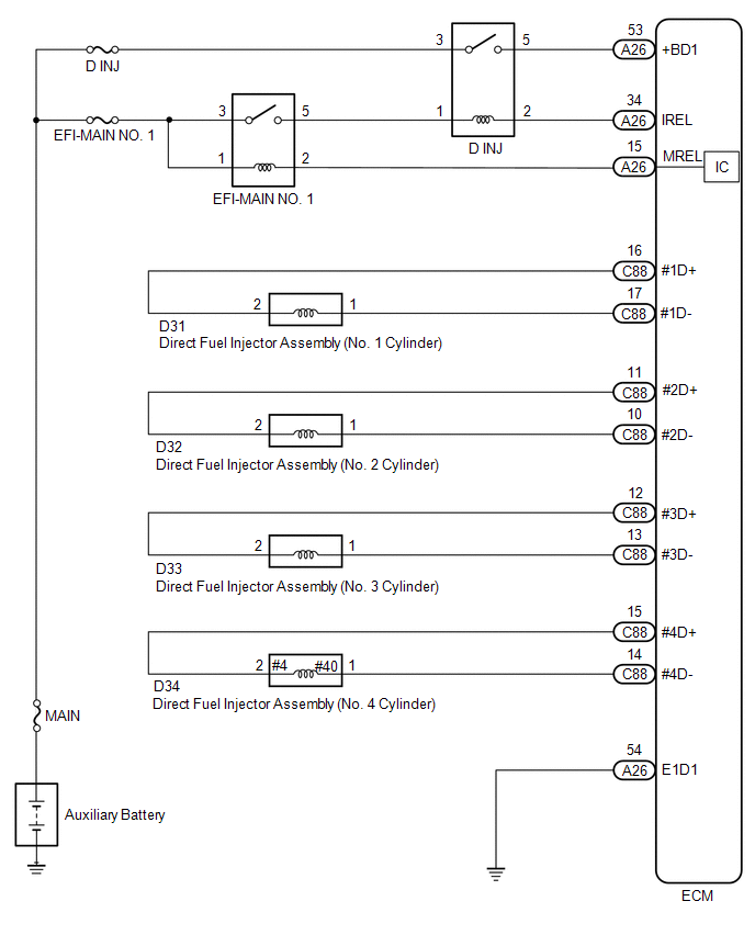
WIRING DIAGRAM
CAUTION / NOTICE / HINT
NOTICE:
- Inspect the fuses for circuits related to this system before performing the following procedure.
-
Vehicle Control History may be stored in the hybrid vehicle control ECU assembly if the engine is malfunctioning. Certain vehicle condition information is recorded when Vehicle Control History is stored. Reading the vehicle conditions recorded in both the Freeze Frame Data and Vehicle Control History can be useful for troubleshooting.
Click here
(Select Powertrain in Health Check and then check the time stamp data.)
Click here
-
If any "Engine Malfunction" Vehicle Control History item has been stored in the hybrid vehicle control ECU assembly, make sure to clear it. However, as all Vehicle Control History items are cleared simultaneously, if any Vehicle Control History items other than "Engine Malfunction" are stored, make sure to perform any troubleshooting for them before clearing Vehicle Control History.
Click here
HINT:
- If the current from the D INJ relay is cut because DTC P062D13 is stored, DTC P123513 will be stored even if the fuel pump assembly (for high pressure side) is normal.
- Read Freeze Frame Data using the Techstream. The ECM records vehicle and driving condition information as Freeze Frame Data the moment a DTC is stored. When troubleshooting, Freeze Frame Data can help determine if the vehicle was moving or stationary, if the engine was warmed up or not, if the air fuel ratio was lean or rich, and other data from the time the malfunction occurred.
PROCEDURE
| 1. | CHECK DTC OUTPUT (DTC P020113, P020213, P020313, P020413 AND/OR P062D13) |
(a) Connect the Techstream to the DLC3.
(b) Turn the power switch on (IG).
(c) Turn the Techstream on.
(d) Enter the following menus: Powertrain / Engine / Trouble Codes.
(e) Read the DTCs.
Powertrain > Engine > Trouble Codes| Result | Proceed to |
|---|---|
| DTC P020113, P020213, P020313 or P020413 is output | A |
| 3 or more of the following DTCs are output: P062D13, P020113, P020213, P020313 and P020413 | B |
| DTC P062D13 is output |
| B | .gif) | GO TO STEP 4 |
|
.gif)
| 2. | CHECK HARNESS AND CONNECTOR |
(a) Disconnect the ECM connector.
(b) Measure the resistance according to the value(s) in the table below.
Standard Resistance:
| Tester Connection | Condition | Specified Condition |
|---|---|---|
| C88-16 (#1D+) - C88-17 (#1D-) | 20°C (68°F) | 1.34 to 1.64 Ω |
| C88-11 (#2D+) - C88-10 (#2D-) | 20°C (68°F) | 1.34 to 1.64 Ω |
| C88-12 (#3D+) - C88-13 (#3D-) | 20°C (68°F) | 1.34 to 1.64 Ω |
| C88-15 (#4D+) - C88-14 (#4D-) | 20°C (68°F) | 1.34 to 1.64 Ω |
| C88-16 (#1D+) or C88-17 (#1D-) - Body ground and other terminals | Always | 1 MΩ or higher |
| C88-11 (#2D+) or C88-10 (#2D-) - Body ground and other terminals | Always | 1 MΩ or higher |
| C88-12 (#3D+) or C88-13 (#3D-) - Body ground and other terminals | Always | 1 MΩ or higher |
| C88-15 (#4D+) or C88-14 (#4D-) - Body ground and other terminals | Always | 1 MΩ or higher |
HINT:
The standard values shown are direct fuel injector assembly resistance values.
| OK | | REPLACE ECM |
|
| 3. | INSPECT DIRECT FUEL INJECTOR ASSEMBLY (RESISTANCE) |
(a) Check the resistance of the direct fuel injector assembly.
Click here
HINT:
Perform "Inspection After Repair" after replacing the direct fuel injector assembly.
Click here
| OK | | REPAIR OR REPLACE HARNESS OR CONNECTOR (DIRECT FUEL INJECTOR ASSEMBLY - ECM) |
| NG | | REPLACE DIRECT FUEL INJECTOR ASSEMBLY |
| 4. | INSPECT D INJ RELAY |
(a) Inspect the D INJ relay.
Click here
| NG | | REPLACE D INJ RELAY |
|
| 5. | CHECK TERMINAL VOLTAGE (POWER SOURCE OF D INJ RELAY) |
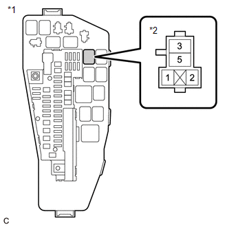
| *1 | No. 1 Engine Room Relay Block and No. 1 Junction Block Assembly |
| *2 | D INJ Relay |
(a) Remove the D INJ relay from the No. 1 engine room relay block and No. 1 junction block assembly.
(b) Measure the voltage according to the value(s) in the table below.
Standard Voltage:
| Tester Connection | Condition | Specified Condition |
|---|---|---|
| 3 (D INJ relay) - Body ground | Always | 11 to 14 V |
| NG | | REPAIR OR REPLACE HARNESS OR CONNECTOR (AUXILIARY BATTERY - D INJ RELAY) |
|
| 6. | CHECK TERMINAL VOLTAGE (POWER SOURCE OF D INJ RELAY) |
| *1 | No. 1 Engine Room Relay Block and No. 1 Junction Block Assembly |
| *2 | D INJ Relay |
(a) Remove the D INJ relay from the No. 1 engine room relay block and No. 1 junction block assembly.
(b) Turn the power switch on (IG).
(c) Measure the voltage according to the value(s) in the table below.
Standard Voltage:
| Tester Connection | Condition | Specified Condition |
|---|---|---|
| 1 (D INJ relay) - Body ground | Power switch on (IG) | 11 to 14 V |
| NG | | REPAIR OR REPLACE HARNESS OR CONNECTOR (EFI-MAIN NO. 1 RELAY - D INJ RELAY) |
|
| 7. | CHECK HARNESS AND CONNECTOR (D INJ RELAY - ECM) |
(a) Remove the D INJ relay from the No. 1 engine room relay block and No. 1 junction block assembly.
(b) Disconnect the ECM connector.
(c) Measure the resistance according to the value(s) in the table below.
Standard Resistance:
| Tester Connection | Condition | Specified Condition |
|---|---|---|
| 5 (D INJ relay) - A26-53 (+BD1) | Always | Below 1 Ω |
| 2 (D INJ relay) - A26-34 (IREL) | Always | Below 1 Ω |
| 5 (D INJ relay) or A26-53 (+BD1) - Body ground and other terminals | Always | 10 kΩ or higher |
| 2 (D INJ relay) or A26-34 (IREL) - Body ground and other terminals | Always | 10 kΩ or higher |
| OK | | REPLACE ECM |
| NG | | REPAIR OR REPLACE HARNESS OR CONNECTOR |
READ NEXT:
 Throttle/Pedal Position Sensor/Switch "B" Circuit Short to Ground (P022011)
DESCRIPTION Refer to DTC P012011. Click here DTC No. Detection Item DTC Detection Condition Trouble Area MIL Memory Note P022011 Throttle/Pedal Position Sensor/Switch "B" Circui
Throttle/Pedal Position Sensor/Switch "B" Circuit Short to Battery or Open (P022015)
DESCRIPTION Refer to DTC P012011. Click here DTC No. Detection Item DTC Detection Condition Trouble Area MIL Memory Note P022015 Throttle/Pedal Position Sensor/Switch "B" Circui
Random/Multiple Cylinder Misfire Detected (P030000,P030027,P030085-P030400)
DESCRIPTION When the engine misfires, high concentrations of hydrocarbons (HC) enter the exhaust gas. Extremely high hydrocarbon concentration levels can cause an increase in exhaust emission levels.
SEE MORE:
Components
COMPONENTS ILLUSTRATION *A for EGR Valve Bracket Connection Type *B for Cylinder Head Cover Sub-assembly Connection Type *1 FUEL PUMP ASSEMBLY *2 NO. 1 FUEL PIPE SUB-ASSEMBLY *3 FUEL TUBE SUB-ASSEMBLY *4 FUEL PUMP LIFTER ASSEMBLY *5 FUEL PUMP FLANGE *6 FUEL PU
Inspection
INSPECTION PROCEDURE 1. INSPECT OIL PRESSURE CONTROL VALVE ASSEMBLY (a) Measure the resistance according to the value(s) in the table below. Standard Resistance: Tester Connection Condition Specified Condition 1 - 2 20°C (68°F) 6.2 to 8.2 Ω If the result is not as specified,
