Lexus ES: Disassembly
DISASSEMBLY
CAUTION / NOTICE / HINT
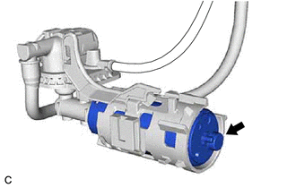
NOTICE:
Do not disconnect the tube shown in the illustration when disassembling the fuel suction tube with pump and gauge assembly. Doing so will cause reassembly of the fuel suction tube with pump and gauge assembly to be impossible as the tube is pressed into the fuel suction plate sub-assembly.
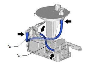
| *a | Tube |
PROCEDURE
1. REMOVE FUEL SENDER GAUGE ASSEMBLY
Click here .gif)
2. REMOVE FUEL PUMP
| (a) Disconnect the 3 fuel pump harness connectors. |
|
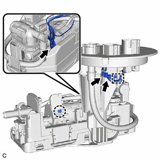
(b) Disengage the claw and disconnect the ground terminal of the fuel pump harness.
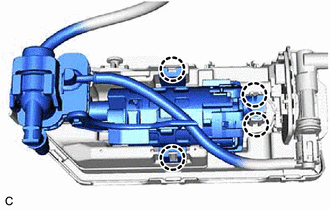
(c) Disengage the clamp to remove the fuel pump harness from the fuel suction tube with pump and gauge assembly.
NOTICE:
- Do not damage the wire harness.
- When disengaging each wire harness from the clamp, disengage one wire at a time.
(d) Disengage the claw and slide the fuel suction plate sub-assembly and then separate it from the fuel sub-tank sub-assembly.

| *1 | Fuel Suction Plate Sub-assembly |
.png) | Pull |
.png) | Slide |
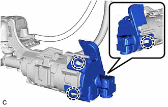
| (e) Disengage the 4 claws and remove the fuel suction plate sub-assembly from the fuel sub-tank sub-assembly. |
|
| (f) Disengage the 3 claws and remove the No. 2 fuel suction support from the fuel suction plate sub-assembly. |
|
| (g) Remove the fuel pump from the fuel suction plate sub-assembly. |
|
| (h) Remove the O-ring and fuel pump spacer from the fuel pump. |
|

READ NEXT:
 Inspection
INSPECTION PROCEDURE 1. INSPECT FUEL PUMP (a) Measure the resistance according to the value(s) in the table below. Standard Resistance: Tester Connection Specified Condition U - V 0.05
Reassembly
REASSEMBLY PROCEDURE 1. INSTALL FUEL PUMP HINT: Perform "Inspection After Repair" after replacing the fuel pump. Click here (a) Apply gasoline to a new O-ring. Then install the O-ring and fuel pu
Installation
INSTALLATION PROCEDURE 1. INSTALL FUEL SUCTION TUBE WITH PUMP AND GAUGE ASSEMBLY (a) Install a new fuel suction tube set gasket to the fuel tank assembly. (b) Connect the fuel return vent tube sub-ass
SEE MORE:
Black Screen
DESCRIPTION The video signal from the rear television camera assembly is transmitted to the multi-display assembly. WIRING DIAGRAM CAUTION / NOTICE / HINT NOTICE:
If the cable was disconnected from and reconnected to the negative (-) battery terminal, the estimated course lines may not be displa
Remote Up / Down Function does not Operate
DESCRIPTION When the power switch on (IG), the multiplex network master switch assembly sends remote up and down signals to each power window regulator motor assembly via LIN communication. WIRING DIAGRAM CAUTION / NOTICE / HINT NOTICE:
The power window control system uses the LIN communication
