Lexus ES: Components
COMPONENTS
ILLUSTRATION
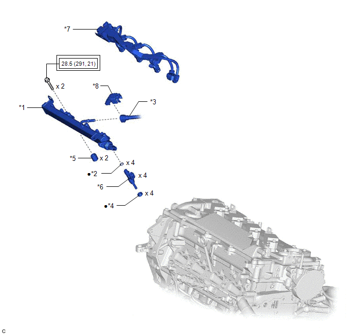
| *1 | FUEL DELIVERY PIPE SUB-ASSEMBLY | *2 | O-RING |
| *3 | FUEL TUBE SUB-ASSEMBLY | *4 | INJECTOR VIBRATION INSULATOR |
| *5 | NO. 1 DELIVERY PIPE SPACER | *6 | PORT FUEL INJECTOR ASSEMBLY |
| *7 | NO. 5 ENGINE WIRE | *8 | FUEL PIPE CLAMP |
.png) | Tightening torque for "Major areas involving basic vehicle performance such as moving/turning/stopping": N*m (kgf*cm, ft.*lbf) | ● | Non-reusable part |
READ NEXT:
 Inspection
INSPECTION PROCEDURE 1. INSPECT PORT FUEL INJECTOR ASSEMBLY (a) Check the resistance. (1) Measure the resistance according to the value(s) in the table below. Standard Resistance: Tester Connec
Installation
INSTALLATION CAUTION / NOTICE / HINT NOTICE: This procedure includes the installation of small-head bolts. Refer to Small-Head Bolts of Basic Repair Hint to identify the small-head bolts. Click here
Fuel Main Valve
ComponentsCOMPONENTS ILLUSTRATION *1 FUEL SUCTION TUBE WITH PUMP AND GAUGE ASSEMBLY *2 FUEL MAIN VALVE ASSEMBLY *3 FUEL PRESSURE REGULATOR HOLDER *4 O-RING ● Non-reusable
SEE MORE:
Components
COMPONENTS ILLUSTRATION *A for Gasoline Model - - *1 NO. 1 FLOOR UNDER COVER *2 NO. 2 FLOOR UNDER COVER N*m (kgf*cm, ft.*lbf): Specified torque - - ILLUSTRATION *1 REAR FLEXIBLE HOSE LH *2 REAR FLEXIBLE HOSE RH *3 REAR STABILIZER BAR *4 REAR STAB
Dtc Check / Clear
DTC CHECK / CLEAR NOTICE: When the diagnosis system is changed from normal mode to check mode or vice versa, all DTCs and freeze frame data recorded in normal mode are cleared. Before changing modes, always check and make a note of DTCs and freeze frame data. HINT:
DTCs which are stored in the EC
© 2016-2026 Copyright www.lexguide.net
