Lexus ES: Installation
INSTALLATION
CAUTION / NOTICE / HINT
NOTICE:
This procedure includes the installation of small-head bolts. Refer to Small-Head Bolts of Basic Repair Hint to identify the small-head bolts.
Click here .gif)
PROCEDURE
1. INSTALL PORT FUEL INJECTOR ASSEMBLY
HINT:
Perform "Inspection After Repair" after replacing a port fuel injector assembly.
Click here
(a) Apply a light coat of spindle oil or gasoline to 4 new O-rings, and install one to each port fuel injector assembly.
NOTICE:
Check that there is no damage or foreign matter on the groove of the port fuel injector assembly when installing the O-ring to each port fuel injector assembly.
| (b) Install the 4 port fuel injector assemblies to the fuel delivery pipe sub-assembly. NOTICE:
|
|
2. INSTALL NO. 5 ENGINE WIRE
(a) Engage the 2 clamps to install the No. 5 engine wire to the fuel delivery pipe sub-assembly.
(b) Connect the 4 port fuel injector assembly connectors and No. 2 fuel pressure sensor connector.
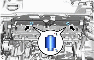
3. INSTALL INJECTOR VIBRATION INSULATOR
(a) Install 4 new injector vibration insulators to the cylinder head sub-assembly.
4. INSTALL NO. 1 DELIVERY PIPE SPACER
| (a) Install the 2 No. 1 delivery pipe spacers to the cylinder head sub-assembly. NOTICE: Install the No. 1 delivery pipe spacers in the correct direction. |
|
5. INSTALL FUEL DELIVERY PIPE SUB-ASSEMBLY
(a) Place the fuel delivery pipe sub-assembly with the 4 port fuel injector assemblies onto the cylinder head sub-assembly.
NOTICE:
Be careful not to drop the port fuel injector assemblies when installing the fuel delivery pipe sub-assembly.
(b) Install the fuel delivery pipe sub-assembly with the port fuel injector assemblies with the 2 bolts.
Torque:
28.5 N·m {291 kgf·cm, 21 ft·lbf}
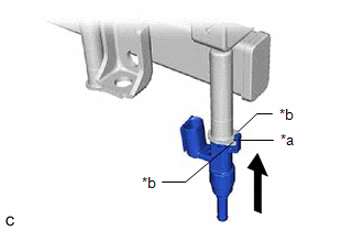
6. CONNECT FUEL TUBE SUB-ASSEMBLY
(a) Connect the fuel tube sub-assembly to the fuel delivery pipe sub-assembly.
Click here
(b) Install the fuel pipe clamp to the fuel tube connector.
7. INSTALL FUEL (ENGINE ROOM SIDE) PUMP ASSEMBLY
Click here
8. PERFORM INITIALIZATION
(a) Perform "Inspection After Repair" after replacing a port fuel injector assembly.
Click here
READ NEXT:
 Fuel Main Valve
ComponentsCOMPONENTS ILLUSTRATION *1 FUEL SUCTION TUBE WITH PUMP AND GAUGE ASSEMBLY *2 FUEL MAIN VALVE ASSEMBLY *3 FUEL PRESSURE REGULATOR HOLDER *4 O-RING ● Non-reusable
Fuel Pressure Sensor
ComponentsCOMPONENTS ILLUSTRATION *1 NO. 2 FUEL PRESSURE SENSOR *2 NO. 2 FUEL PRESSURE SENSOR HOLDER *3 O-RING - - Tightening torque for "Major areas involving basic vehicl
SEE MORE:
Customize Parameters
CUSTOMIZE PARAMETERS CUSTOMIZE HEATED STEERING WHEEL SYSTEM (a) Customizing with the Techstream. NOTICE:
When the customer requests a change in a function, first make sure that the function can be customized.
Be sure to make a note of the current settings before customizing.
When troubleshoot
Remote Control System does not Operate
DESCRIPTION The main body ECU (multiplex network body ECU) receives remote control signals from the driver door key cylinder or electrical key transmitter sub-assembly. Then, the main body ECU (multiplex network body ECU) activates the power window motor and sends the remote control signals to the s
