Lexus ES: Components
COMPONENTS
ILLUSTRATION
.png)
| *A | for Gasoline Model | - | - |
| *1 | NO. 1 FLOOR UNDER COVER | *2 | NO. 2 FLOOR UNDER COVER |
.png) | N*m (kgf*cm, ft.*lbf): Specified torque | - | - |
ILLUSTRATION
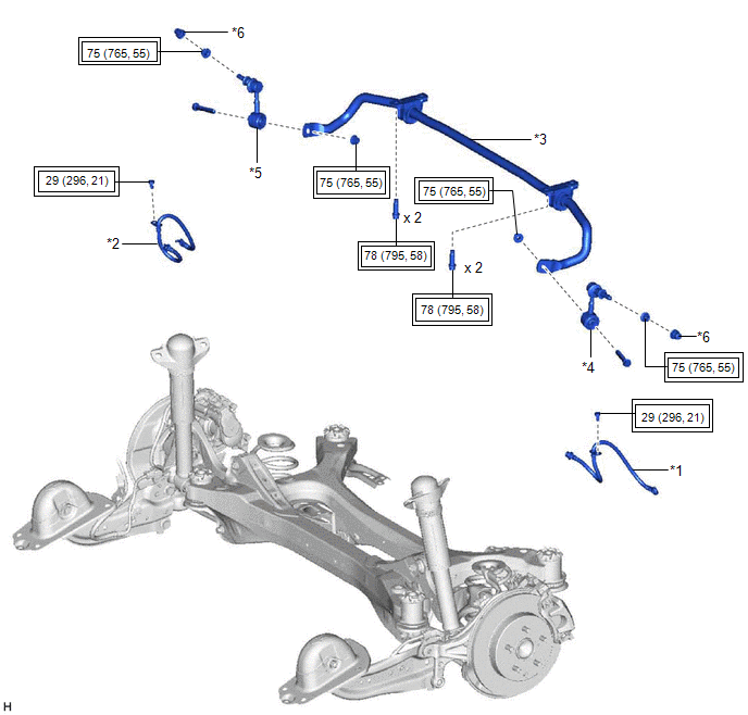
| *1 | REAR FLEXIBLE HOSE LH | *2 | REAR FLEXIBLE HOSE RH |
| *3 | REAR STABILIZER BAR | *4 | REAR STABILIZER LINK ASSEMBLY LH |
| *5 | REAR STABILIZER LINK ASSEMBLY RH | *6 | CAP |
.png) | Tightening torque for "Major areas involving basic vehicle performance such as moving/turning/stopping": N*m (kgf*cm, ft.*lbf) | - | - |
ILLUSTRATION
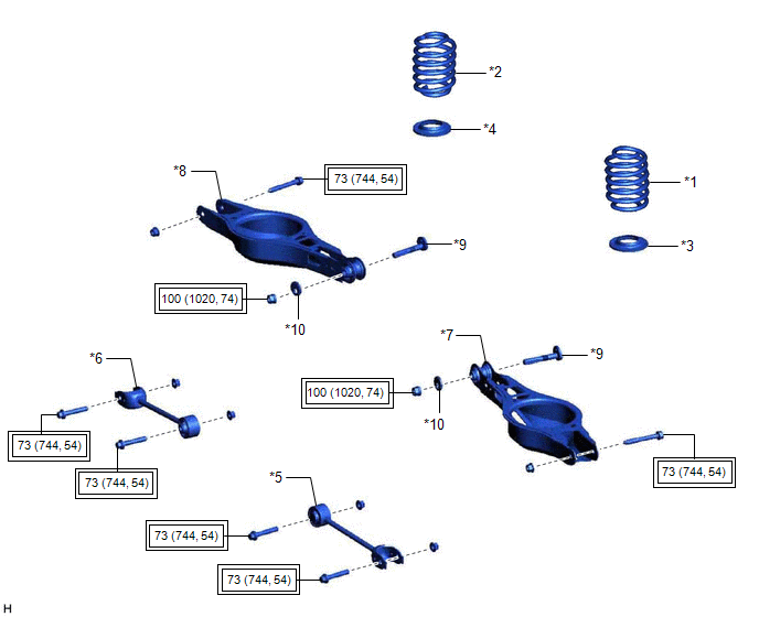
| *1 | REAR COIL SPRING LH | *2 | REAR COIL SPRING RH |
| *3 | REAR LOWER COIL SPRING INSULATOR LH | *4 | REAR LOWER COIL SPRING INSULATOR RH |
| *5 | REAR NO. 1 SUSPENSION ARM ASSEMBLY LH | *6 | REAR NO. 1 SUSPENSION ARM ASSEMBLY RH |
| *7 | REAR NO. 2 SUSPENSION ARM ASSEMBLY LH | *8 | REAR NO. 2 SUSPENSION ARM ASSEMBLY RH |
| *9 | REAR SUSPENSION TOE ADJUST CAM SUB-ASSEMBLY | *10 | NO. 2 CAMBER ADJUST CAM |
| | Tightening torque for "Major areas involving basic vehicle performance such as moving/turning/stopping": N*m (kgf*cm, ft.*lbf) | - | - |
ILLUSTRATION
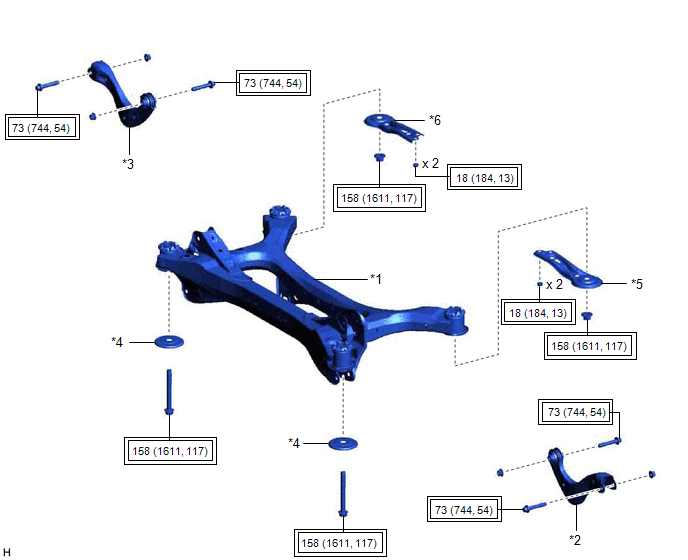
| *1 | REAR SUSPENSION MEMBER SUB-ASSEMBLY | *2 | REAR UPPER CONTROL ARM ASSEMBLY LH |
| *3 | REAR UPPER CONTROL ARM ASSEMBLY RH | *4 | REAR SUSPENSION MEMBER LOWER STOPPER |
| *5 | REAR SUSPENSION MEMBER LOWER BRACE LH | *6 | REAR SUSPENSION MEMBER LOWER BRACE RH |
| | Tightening torque for "Major areas involving basic vehicle performance such as moving/turning/stopping": N*m (kgf*cm, ft.*lbf) | - | - |
ILLUSTRATION
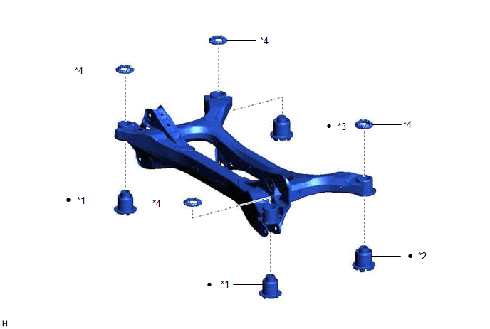
| *1 | REAR SUSPENSION MEMBER FRONT BODY MOUNTING CUSHION | *2 | REAR SUSPENSION MEMBER REAR BODY MOUNT CUSHION LH |
| *3 | REAR SUSPENSION MEMBER REAR BODY MOUNT CUSHION RH | *4 | REAR SUSPENSION MEMBER CUSHION |
| ● | Non-reusable part | - | - |
READ NEXT:
 Removal
REMOVAL CAUTION / NOTICE / HINT The necessary procedures (adjustment, calibration, initialization, or registration) that must be performed after parts are removed and installed, or replaced during rea
Installation
INSTALLATION PROCEDURE 1. INSTALL REAR SUSPENSION MEMBER FRONT BODY MOUNTING CUSHION (for LH Side) (a) Confirm the installation direction and temporarily install a new rear suspension member front bod
SEE MORE:
Open in B Power Line (B242F)
DESCRIPTION The headlight ECU sub-assembly operates using the power source voltage input from the IG terminal and ECUB terminal. The power source voltage of the ECUB terminal is supplied when the main body ECU (multiplex network body ECU) turns the ECUB power supply relay (H-LP LH relay and H-LP RH
Problem Symptoms Table
PROBLEM SYMPTOMS TABLE HINT:
Use the table below to help determine the cause of problem symptoms. If multiple suspected areas are listed, the potential causes of the symptoms are listed in order of probability in the "Suspected Area" column of the table. Check each symptom by checking the suspect
