Lexus ES: Fuel Main Valve
Components
COMPONENTS
ILLUSTRATION
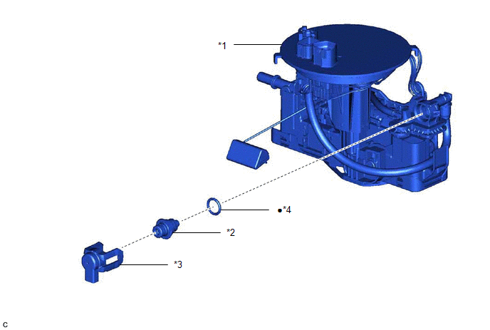
| *1 | FUEL SUCTION TUBE WITH PUMP AND GAUGE ASSEMBLY | *2 | FUEL MAIN VALVE ASSEMBLY |
| *3 | FUEL PRESSURE REGULATOR HOLDER | *4 | O-RING |
| ● | Non-reusable part | - | - |
Installation
INSTALLATION
PROCEDURE
1. INSTALL FUEL MAIN VALVE ASSEMBLY
(a) Apply gasoline to a new O-ring. Then install the O-ring to the fuel main valve assembly.
NOTICE:
Make sure that there is no clearance between the fuel main valve assembly and mesh.
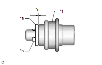
| *1 | Fuel Main Valve Assembly |
| *a | Mesh |
| *b | Mini-clip |
| *c | No Clearance |
(b) Install the fuel main valve assembly to the fuel suction tube with pump and gauge assembly.
NOTICE:
Make sure that the O-ring is not cut or pinched during installation.
2. INSTALL FUEL PRESSURE REGULATOR HOLDER
(a) Engage the 2 claws to install the fuel pressure regulator holder to the fuel suction tube with pump and gauge assembly.
3. INSTALL FUEL SUCTION TUBE WITH PUMP AND GAUGE ASSEMBLY
Click here .gif)
READ NEXT:
 Fuel Pressure Sensor
ComponentsCOMPONENTS ILLUSTRATION *1 NO. 2 FUEL PRESSURE SENSOR *2 NO. 2 FUEL PRESSURE SENSOR HOLDER *3 O-RING - - Tightening torque for "Major areas involving basic vehicl
Components
COMPONENTS ILLUSTRATION *1 FUEL PRESSURE SENSOR *2 NO. 1 FUEL PRESSURE SENSOR HOLDER Tightening torque for "Major areas involving basic vehicle performance such as moving/turning/stop
SEE MORE:
Steering Angle Sensor Failure (C1626)
DESCRIPTION
This DTC is stored if the parking assist ECU receives a signal via CAN communication from the steering sensor that indicates an internal malfunction.
This DTC is stored if the rear television camera assembly receives a signal via CAN communication from the steering sensor that indic
Installation
INSTALLATION CAUTION / NOTICE / HINT NOTICE:
Immediately after installing the brake pads, the braking performance may be reduced. Always perform a road test in a safe place while paying attention to the surroundings.
After replacing the front disc brake pads, the brake pedal may feel soft due t
