Lexus ES: Components
COMPONENTS
ILLUSTRATION
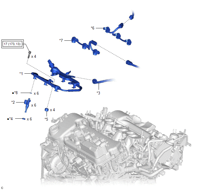
| *1 | FUEL DELIVERY PIPE WITH SENSOR ASSEMBLY | *2 | PORT FUEL INJECTOR ASSEMBLY |
| *3 | FUEL TUBE SUB-ASSEMBLY | *4 | INJECTOR VIBRATION INSULATOR |
| *5 | NO. 1 DELIVERY PIPE SPACER | *6 | NO. 5 ENGINE WIRE (for Bank 1) |
| *7 | NO. 5 ENGINE WIRE (for Bank 2) | *8 | O-RING |
.png) | Tightening torque for "Major areas involving basic vehicle performance such as moving/turning/stopping": N*m (kgf*cm, ft.*lbf) | ● | Non-reusable part |
READ NEXT:
 Removal
REMOVAL CAUTION / NOTICE / HINT The necessary procedures (adjustment, calibration, initialization or registration) that must be performed after parts are removed and installed, or replaced during port
Inspection
INSPECTION PROCEDURE 1. INSPECT PORT FUEL INJECTOR ASSEMBLY (a) Check the resistance. (1) Measure the resistance according to the value(s) in the table below. Standard Resistance: Tester Connec
Installation
INSTALLATION PROCEDURE 1. INSTALL PORT FUEL INJECTOR ASSEMBLY HINT: Perform "Inspection After Repair" after replacing a port fuel injector assembly. Click here (a) Apply a light coat of spindle oil
SEE MORE:
Parts Location
PARTS LOCATION ILLUSTRATION *1 DEF RELAY *2 REAR WINDOW DEFOGGER WIRE *3 NO. 1 ENGINE ROOM RELAY BLOCK AND NO. 1 JUNCTION BLOCK ASSEMBLY - DEF FUSE *4 BACK WINDOW GLASS ILLUSTRATION *1 REAR WINDOW DEFOGGER SWITCH (AIR CONDITIONING CONTROL ASSEMBLY) *2 DLC3 *3 A
Motor Shutdown Stuck Off (P1C6A9F)
DTC SUMMARY MALFUNCTION DESCRIPTION The hybrid vehicle control ECU detects malfunctions which prevent the motor (MG2) inverter shutdown circuit shutting down the hybrid vehicle control system. Detection is performed during the shutdown sequence when the power switch is turned off. If motor (MG2) inv
© 2016-2026 Copyright www.lexguide.net
