Lexus ES: Installation
INSTALLATION
PROCEDURE
1. INSTALL PORT FUEL INJECTOR ASSEMBLY
HINT:
Perform "Inspection After Repair" after replacing a port fuel injector assembly.
Click here .gif)
(a) Apply a light coat of spindle oil or gasoline to 6 new O-rings, and install one to each port fuel injector assembly.
NOTICE:
Check that there is no damage or foreign matter on the groove of the port fuel injector assembly when installing the O-ring to each port fuel injector assembly.
(b) for Bank 1:
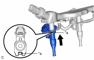
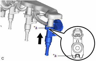
(1) Connect the 3 port fuel injector assembly connectors.
| (2) Install the 3 port fuel injector assemblies to the fuel delivery pipe with sensor assembly. NOTICE:
|
|
(3) Engage the clamp to connect the No. 5 engine wire to the fuel delivery pipe with sensor assembly.
(c) for Bank 2:
(1) Connect the 3 port fuel injector assembly connectors.
| (2) Install the 3 port fuel injector assemblies to the fuel delivery pipe with sensor assembly. NOTICE:
|
|
(3) Engage the clamp to connect the No. 5 engine wire to the fuel delivery pipe with sensor assembly.
2. INSTALL INJECTOR VIBRATION INSULATOR
(a) Install 6 new injector vibration insulators to the intake manifold.
3. INSTALL NO. 1 DELIVERY PIPE SPACER
(a) Install the 4 No. 1 delivery pipe spacers to the intake manifold.
4. INSTALL FUEL DELIVERY PIPE WITH SENSOR ASSEMBLY
(a) Place the fuel delivery pipe with sensor assembly with the 6 port fuel injector assemblies onto the intake manifold.
NOTICE:
Be careful not to drop the port fuel injector assemblies when installing the fuel delivery pipe with sensor assembly.
(b) Install the fuel delivery pipe with sensor assembly with the 6 port fuel injector assemblies to the intake manifold with the 4 bolts.
Torque:
17 N·m {173 kgf·cm, 13 ft·lbf}
(c) Connect the 2 No. 5 engine wire connectors.
(d) Connect the fuel pressure sensor connector.
5. CONNECT FUEL TUBE SUB-ASSEMBLY
(a) Connect the fuel tube sub-assembly to the fuel delivery pipe with sensor assembly.
Click here
6. INSTALL INTAKE AIR SURGE TANK ASSEMBLY
Click here
7. CONNECT CABLE TO NEGATIVE BATTERY TERMINAL
Click here
8. INSPECT FOR FUEL LEAK
Click here
9. PERFORM INITIALIZATION
(a) Perform "Inspection After Repair" after replacing a port fuel injector assembly.
Click here
READ NEXT:
 Components
COMPONENTS ILLUSTRATION *1 FUEL SUCTION PLATE SUB-ASSEMBLY *2 FUEL FILTER *3 O-RING *4 FUEL MAIN VALVE ASSEMBLY (for Low Pressure) *5 FUEL MAIN VALVE ASSEMBLY (for High Press
Removal
REMOVAL CAUTION / NOTICE / HINT The necessary procedures (adjustment, calibration, initialization or registration) that must be performed after parts are removed and installed, or replaced during fuel
SEE MORE:
Installation
INSTALLATION PROCEDURE 1. INSTALL ACCELERATOR PEDAL ASSEMBLY (a) Engage the claw to install the accelerator pedal assembly. (b) Install the 2 bolts. Torque: 7.5 N·m {76 kgf·cm, 66 in·lbf} 2. INSTALL ACCELERATOR PEDAL PAD (a) Engage the 4 claws to install the accelerator pedal pad
Touch Pad Vibration Driver Malfunction (B155A)
DESCRIPTION This DTC is stored if the remote touch (remote operation controller assembly) detects a malfunction in itself, such as internal hardware failure or remote touch screen vibration driver malfunction. DTC No. Detection Item DTC Detection Condition Trouble Area B155A Touch Pad
