Lexus ES: Removal
REMOVAL
CAUTION / NOTICE / HINT
The necessary procedures (adjustment, calibration, initialization or registration) that must be performed after parts are removed and installed, or replaced during port fuel injector assembly removal/installation are shown below.
Necessary Procedures After Parts Removed/Installed/Replaced| Replaced Part or Performed Procedure | Necessary Procedure | Effect/Inoperative Function when Necessary Procedure not Performed | Link |
|---|---|---|---|
|
*: When performing learning using the Techstream.
Click here | |||
| Battery terminal is disconnected/reconnected | Perform steering sensor zero point calibration | Lane Control System (for Gasoline Model) | |
| Pre-collision System (for Gasoline Model) | |||
| Parking Support Brake System (for Gasoline Model)* | |||
| Lighting System (for Gasoline Model) | |||
| Memorize steering angle neutral point | Parking Assist Monitor System (for Gasoline Model) | | |
| Panoramic View Monitor System (for Gasoline Model) | | ||
| Initialize power trunk lid system | Power Trunk Lid System (for Gasoline Model) | | |
| Inspection after repair |
| |
CAUTION:
-
Never perform work on fuel system components near any possible ignition sources.
.png)
- Vaporized fuel could ignite, resulting in a serious accident.
-
Do not perform work on fuel system components without first disconnecting the cable from the negative (-) battery terminal.
.png)
- Sparks could cause vaporized fuel to ignite, resulting in a serious accident.
NOTICE:
- After the engine switch is turned off, the radio receiver assembly records various types of memory and settings. As a result, after turning the engine switch off, make sure to wait at least 85 seconds before disconnecting the cable from the negative (-) battery terminal. (for Audio and Visual System)
- After the engine switch is turned off, the radio receiver assembly records various types of memory and settings. As a result, after turning the engine switch off, make sure to wait at least 85 seconds before disconnecting the cable from the negative (-) battery terminal. (for Navigation System)
PROCEDURE
1. PRECAUTION
NOTICE:
After turning the engine switch off, waiting time may be required before disconnecting the cable from the negative (-) battery terminal. Therefore, make sure to read the disconnecting the cable from the negative (-) battery terminal notices before proceeding with work.
2. DISCHARGE FUEL SYSTEM PRESSURE
Click here .gif)
3. DISCONNECT CABLE FROM NEGATIVE BATTERY TERMINAL
Click here
4. REMOVE INTAKE AIR SURGE TANK ASSEMBLY
Click here
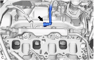
5. DISCONNECT FUEL TUBE SUB-ASSEMBLY
| (a) Disconnect the fuel tube sub-assembly from the fuel delivery pipe with sensor assembly. Click here |
|
6. REMOVE FUEL DELIVERY PIPE WITH SENSOR ASSEMBLY
| (a) Disconnect the fuel pressure sensor connector. |
|
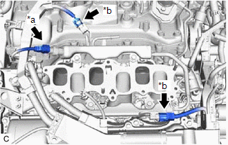
(b) Disconnect the 2 No. 5 engine wire connectors.
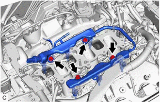
| (c) Remove the 4 bolts and fuel delivery pipe with sensor assembly with the 6 port fuel injector assemblies from the intake manifold. NOTICE:
|
|
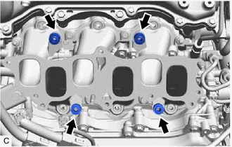
7. REMOVE NO. 1 DELIVERY PIPE SPACER
| (a) Remove the 4 No. 1 delivery pipe spacers from the intake manifold. |
|
8. REMOVE INJECTOR VIBRATION INSULATOR
| (a) Remove the 6 injector vibration insulators from the intake manifold. |
|

9. REMOVE PORT FUEL INJECTOR ASSEMBLY
(a) for Bank 2:
| (1) Disengage the clamp to disconnect the No. 5 engine wire from the fuel delivery pipe with sensor assembly. |
|
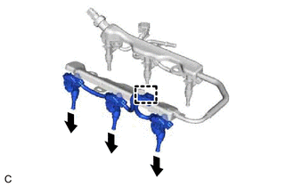
(2) Pull the 3 port fuel injector assemblies out of the fuel delivery pipe with sensor assembly.
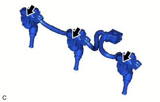
| (3) Disconnect the 3 port fuel injector assembly connectors. |
|
(b) for Bank 1:
| (1) Disengage the clamp to disconnect the No. 5 engine wire from the fuel delivery pipe with sensor assembly. |
|
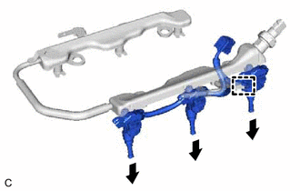
(2) Pull the 3 port fuel injector assemblies out of the fuel delivery pipe with sensor assembly.
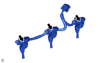
| (3) Disconnect the 3 port fuel injector assembly connectors. |
|
(c) Remove the O-ring from each port fuel injector assembly.
| (d) Attach a tag or label with the corresponding cylinder number to each port fuel injector assembly so that they can be installed to their original locations. NOTICE: Cover the port fuel injector assemblies with plastic bags to prevent damage and contamination. |
|
READ NEXT:
 Inspection
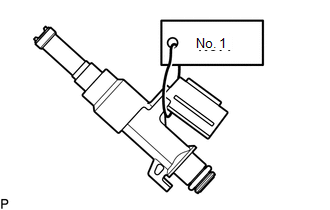
INSPECTION PROCEDURE 1. INSPECT PORT FUEL INJECTOR ASSEMBLY (a) Check the resistance. (1) Measure the resistance according to the value(s) in the table below. Standard Resistance: Tester Connec
Installation
INSTALLATION PROCEDURE 1. INSTALL PORT FUEL INJECTOR ASSEMBLY HINT: Perform "Inspection After Repair" after replacing a port fuel injector assembly. Click here (a) Apply a light coat of spindle oil
SEE MORE:
Automatic High Beam Camera (B124C)
DESCRIPTION The main body ECU (multiplex network body ECU) detects a high beam headlight illumination request signal of the automatic high beam system from the forward recognition camera. DTC No. Detection Item DTC Detection Condition Trouble Area DTC Output from B124C Automatic Hig
Problem Symptoms Table
PROBLEM SYMPTOMS TABLE If DTCs are not output but the malfunction persists, use the following table to determine which circuits to inspect for each problem symptom. HINT: Refer to each inspection procedure for related problem symptoms. Electronically Controlled Brake System Symptom Suspected Ar
