Lexus ES: Parts Location
Lexus ES (XZ10) Service Manual / Vehicle Interior / Window / Glass / Window Defogger System (for Gasoline Model) / Parts Location
PARTS LOCATION
ILLUSTRATION
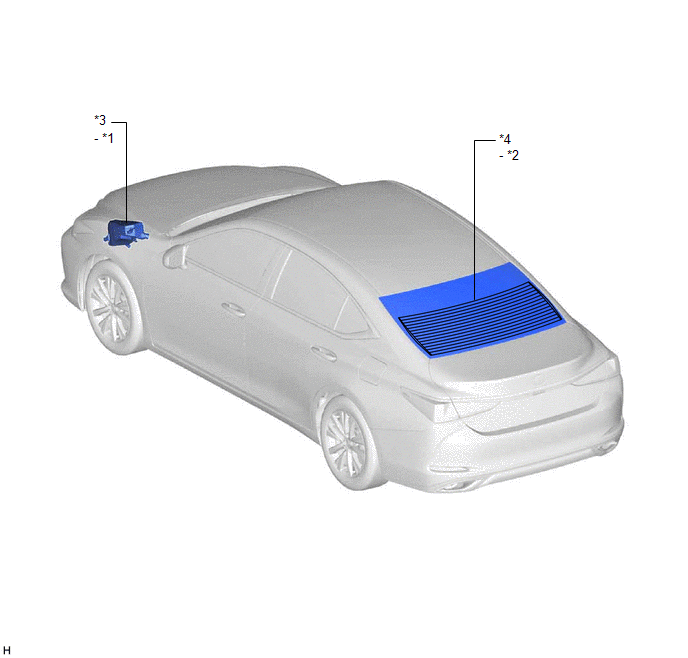
| *1 | DEF RELAY | *2 | REAR WINDOW DEFOGGER WIRE |
| *3 | NO. 1 ENGINE ROOM RELAY BLOCK AND NO. 1 JUNCTION BLOCK ASSEMBLY - DEF FUSE | *4 | BACK WINDOW GLASS |
ILLUSTRATION
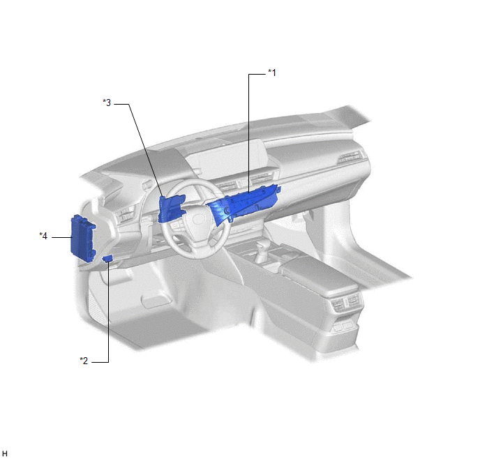
| *1 | REAR WINDOW DEFOGGER SWITCH (AIR CONDITIONING CONTROL ASSEMBLY) | *2 | DLC3 |
| *3 | AIR CONDITIONING AMPLIFIER ASSEMBLY | *4 | INSTRUMENT PANEL JUNCTION BLOCK ASSEMBLY - ECU-IG1 NO. 3 FUSE |
READ NEXT:
 System Diagram
SYSTEM DIAGRAM Communication Table Transmitter Receiver Signal Communication Method Rear Window Defogger Switch (Air Conditioning Control Assembly) Air Conditioning Amplifier Assembly
System Description
SYSTEM DESCRIPTION GENERAL (a) The rear window defogger wire (back window glass) is attached to the inside of the rear window and defogs the window surface quickly when the rear window defogger switch
How To Proceed With Troubleshooting
CAUTION / NOTICE / HINT HINT:
Use the following procedure to troubleshoot the window defogger system.
*: Use the Techstream.
PROCEDURE 1. VEHICLE BROUGHT TO WORKSHOP
NEXT
SEE MORE:
High Voltage System Interlock Circuit Open (P0A0A13,P0A0A92)
DTC SUMMARY MALFUNCTION DESCRIPTION The hybrid vehicle control ECU detects that a safety device (interlock) is operated or that there is an open circuit in the detection circuit. (Even if an open circuit occurs while the vehicle is stopped, the system determines that the safety device was operated.)
Data List / Active Test
DATA LIST / ACTIVE TEST DATA LIST NOTICE:
Some Data List values may vary significantly if there are slight differences in the environment in which the vehicle is operating when measurements are obtained. Variations may also occur due to aging of the vehicle. Due to these considerations, it is not
© 2016-2026 Copyright www.lexguide.net
